
Illumination System Comprising Color Deficiency Compensating Luminescent Material

a luminescent material and color deficiency technology, applied in the direction of discharge tube/lamp details, discharge tube luminescnet screens, lighting and heating apparatus, etc., can solve the problem of unnatural pinkish light, limitation of such phosphor-convertible light-emitting devices, and inability to generate white light of the desired tone, etc. problem, to achieve the effect of improving color rendering and low color temperatur

Active Publication Date: 2008-08-21
LUMILEDS
View PDF7 Cites 25 Cited by
  • Summary
  • Abstract
  • Description
  • Claims
  • Application Information

AI Technical Summary

Benefits of technology

[0013]Consequently, there is a continued need for an efficient and inexpensive solid-state illumination system that is capable of producing white light with a higher CRI, so that objects illuminated by this illumination system appear more natural to the human eye.
[0021]While such illumination systems have a simple design, they achieve both a high efficacy and a high color rendering index with low manufacturing cost and high yield and without substantial color shifting, lifetime, or differential aging problems.
[0029]These specific phosphor blends are especially valuable in white light-emitting phosphor-converted LEDs with low color temperature and improved color rendering.

Problems solved by technology

However, when generating white light from an arrangement of monochromatic red, green and blue light-emitting diodes, there is such a problem that white light of the desired tone cannot be generated due to lifetime variations of the tone, luminance and other factors of the light-emitting diodes.
A limitation of such phosphor-converted light-emitting devices stems from a low color rendition.
Nevertheless, the addition of red radiation to a blue-yellow spectrum for the purpose of “color correcting” or lowering the CCT (Correlated Color Temperature) of its white light emission often results in light that appears unnaturally pinkish and lowers the color contrast between adjacent objects or in printed images having different colors.

Method used


Image

  • Illumination System Comprising Color Deficiency Compensating Luminescent Material
  • Illumination System Comprising Color Deficiency Compensating Luminescent Material
  • Illumination System Comprising Color Deficiency Compensating Luminescent Material

Examples


specific embodiments

[0073]1. White LED Comprising YAG:2% Ce and YAG:1% Pr

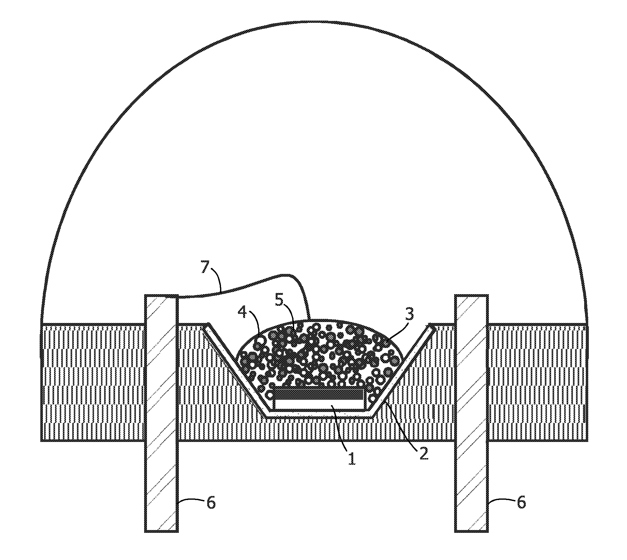
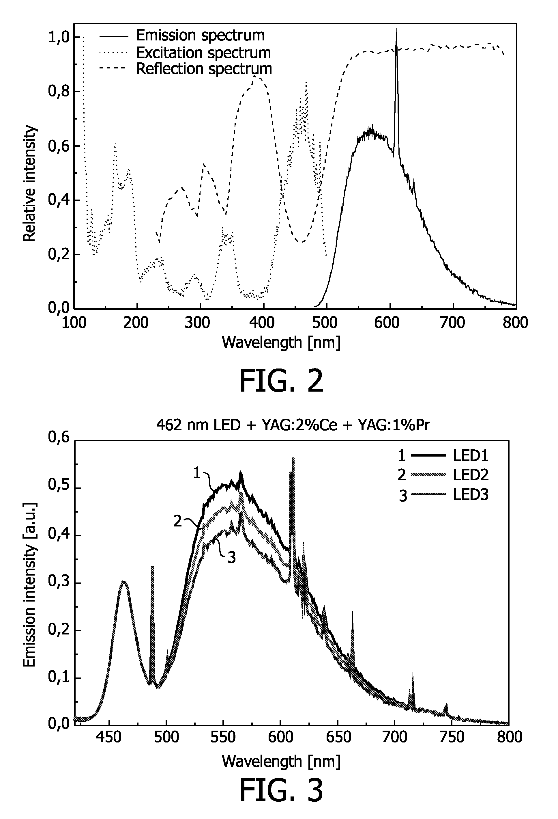
[0074]A phosphor blend of 70 to 80% YAG:2% Ce and 20 to 30% YAG: 1% Pr was suspended in a silicone precursor, a polymerization catalyst was added, and a droplet of this suspension was deposited onto the LED die, based on a 460 nm emitting InGaN. A plastic cap sealed the LED and the silicone was polymerized within about an hour. The spectra of LEDs with three different coating thicknesses are depicted in FIG. 3.

[0075]2. White LED Comprising (Y,Gd)AG:2% Ce and (Y,Gd)AG:1% Pr

[0076]A phosphor blend of 70 to 80% (Y,Gd)AG:2% Ce and 20 to 30% (Y,Gd)AG:1% Pr was suspended in a silicone precursor, a polymerization catalyst was added, and a droplet of this suspension was deposited onto the LED die, based on a 460 nm emitting InGaN. A plastic cap sealed the LED and the silicone was polymerized within about an hour. The spectra of LEDs with two different coating thicknesses are depicted in FIG. 4.

[0077]According to a further aspect of the inv...


PUM


Abstract

In order to improve the color rendition of solid-state illumination devices, an illumination system comprising a radiation source capable of emitting primary radiation and a luminescent material comprising a blend of a first phosphor capable of converting the primary radiation into a broad-band emission in the yellow range of the electromagnetic spectrum and a second phosphor capable of converting the primary radiation into a multiple narrow-band emission in the red and green range of the electromagnetic spectrum is provided.

Description

FIELD OF THE INVENTION[0001]The invention relates to an illumination system and a luminescent material comprising a phosphor blend for generating specific, colored light, including white light, by means of luminescent down-conversion and additive color mixing based on an ultraviolet or blue radiation-emitting radiation source. A light-emitting diode is especially envisaged as a radiation source. The invention also relates to a luminescent material for use in such an illumination system.BACKGROUND OF THE INVENTION[0002]Recently, various attempts have been made to provide illumination systems emitting white light by using light-emitting diodes as radiation sources.[0003]A first category of illumination systems emitting white light by using light-emitting diodes is based on the use of multiple visible light-emitting diodes. In these systems, two monochromatic LEDs (e.g. blue and yellow) or three monochromatic LEDs (e.g. red, blue and green) are used in combination. The light from the m...

Claims


Application Information

Patent Timeline
IPC IPC(8): C09K11/77H01L33/00H01L33/50
CPCC09K11/7706C09K11/7769C09K11/7774C09K11/7776H01L33/502H01L2224/8592H01L33/504H01L2224/48091H01L2924/00014
Inventor JUSTEL, THOMASMAYR, WALTERMEYER, JORGSCHMIDT, PETER
Owner LUMILEDS
Learn More