Optical rotating data transmission device with an unobstructed diameter

a transmission device and optical technology, applied in the field of optical transmission devices, can solve the problems of inability to circumfer the device, inability to effectively solve the bandwidth limitation problem, and inability to achieve the circumference of the device, etc., to achieve low optical attenuation, high data rate, and high mechanical speed of movement

Inactive Publication Date: 2008-05-20
SCHLEIFRING & APPBAU
View PDF18 Cites 2 Cited by
  • Summary
  • Abstract
  • Description
  • Claims
  • Application Information

AI Technical Summary

Benefits of technology

[0011]The invention is based on the object of designing a relatively low-cost device for transmitting optical signals between two units that are rotatable relative to each other, and also a device for coupling-in optical signals into optical rotary joints in such manner that reliable transmission becomes possible with low optical attenuation for large diameters, high mechanical speeds of movement, and high data rates. It is another object of the invention to develop further a device of this kind so that signals are transmitted at a defined polarization. Furthermore, it is the object of a special development of the invention to design the device in such manner that even signals having period durations which are small in comparison with the time of propagation of the light around the circumference of the device may be transmitted.

Problems solved by technology

A basic problem existing here is that of designing a means for carrying light along the circumference of the device, and also suitable means for coupling light in and out.
Wideband data transmission with period lengths of a modulation signal which are substantially smaller than the transit time of the light around the circumference of the device is not possible, because a multiple-path reception of signals occurs at positions of a receiver close to a transmitter.
However, this patent specification describes no effective solution of the problem of bandwidth limitation.
In addition, the proposed coupling-in or coupling-out of light by blunt fiber ends can be achieved only with an extremely poor efficiency.
However, here too a large attenuation of the optical transmission path results, because the coupling-in mirrors cannot be placed arbitrarily close to the mirror-finished cylinder, in particular at high speeds of movement.
Finally, the problem of bandwidth limitation is not solved.
Here too the limitation applies that the period length of the modulation signal must be substantially smaller than the transit time of the light around the circumference of the device.
However, this system involves much outlay, is expensive to fabricate, and is suitable only for small diameters.
Furthermore, here too the wideband problem has not been solved.

Method used


Image

  • Optical rotating data transmission device with an unobstructed diameter
  • Optical rotating data transmission device with an unobstructed diameter
  • Optical rotating data transmission device with an unobstructed diameter

Examples


Embodiment Construction

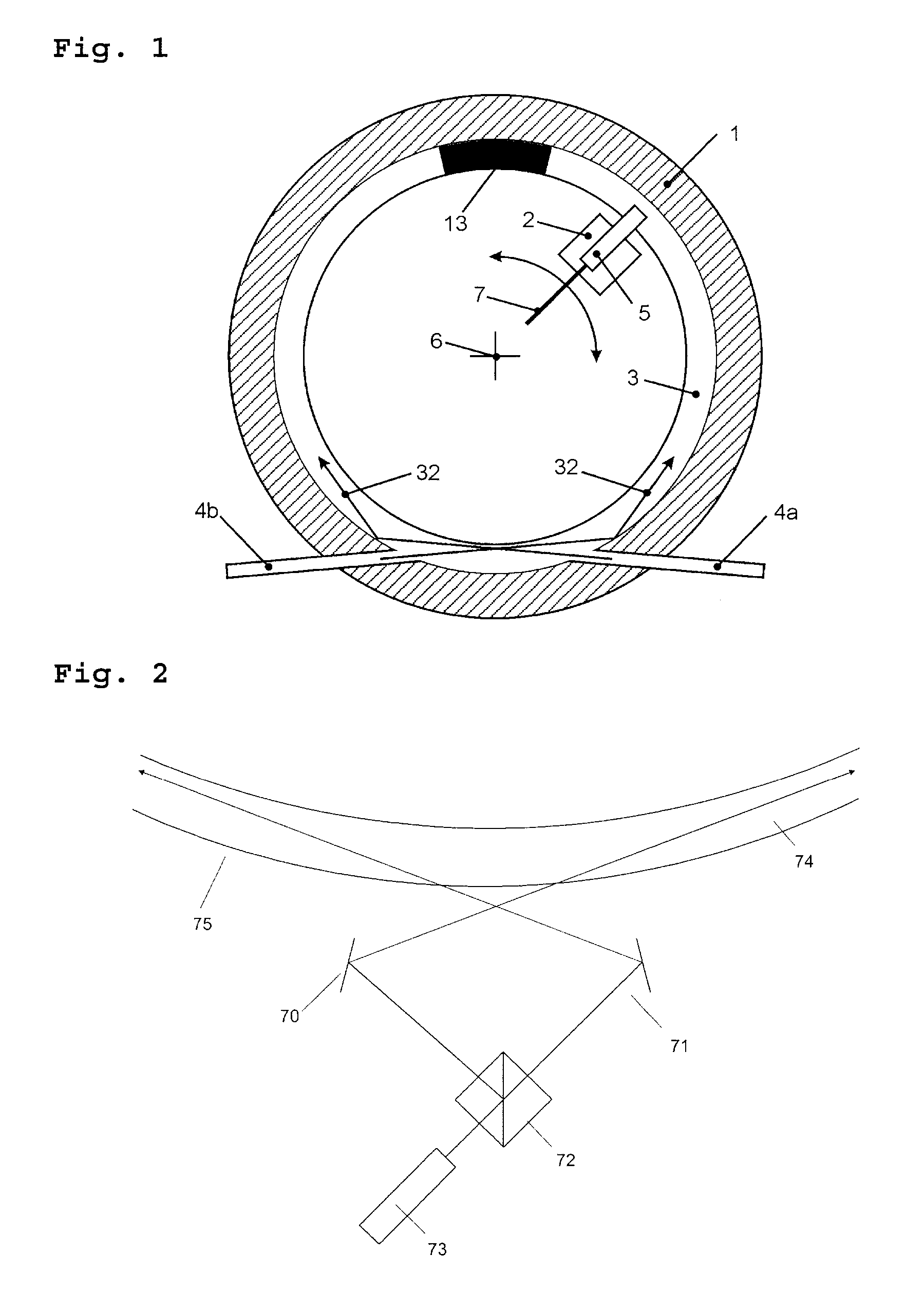
[0018]FIG. 1 shows in a schematic form a plan view of a part of a device according to the invention. A first unit (1) serves to accommodate an annular light guide (3). This light guide is, for example, a trench that is mirror-coated on the inside. A second unit (2) rotates relative to the first unit about a rotation axis (6). The second unit contains a second light coupler (5). The operation will now be illustrated separately for the two respective transmission directions from the first unit to the second unit, and from the second unit to the first unit. Transmission from the first unit to the second unit: light from a not illustrated transmitter is fed into the light guide (3) by means of both parts of a first light coupler (4a, 4b) at the same phase with respect to the modulation signal. On the right-hand side of the illustration the light from the first light coupler (4a) travels as far as the absorber (13). Simultaneously the light from the first light coupler (4b) travels as fa...


PUM


Abstract

A device for transmitting modulated optical signals between a first unit and a second unit, in which the first unit is supported to be rotatable relative to the second unit, comprises a light guide along a circular track on the first unit, a first light coupler for coupling light into or out of the light guide, and a second light coupler disposed on the second unit and movable relative to the light guide, for coupling light into or out of the light guide. A coupling of light into the light guide is effected by means of a beam splitters and a light deflecting means.

Description

CROSS REFERENCE TO RELATED APPLICATIONS[0001]This application is a continuation of pending International Application No. PCT / EP2004 / 011283 filed Oct. 8, 2004, which designated the United States and claims priority from pending German Application No. 10 2004 037 684.0 filed Aug. 2, 2004.BACKGROUND OF THE INVENTION[0002]1. Field of the Invention[0003]The invention relates to a device for transmitting optical signals between units that are rotatable relative to each other. Devices of this kind are used preferably in computer tomographs.[0004]2. Description of the Prior Art[0005]Various devices are known for transmitting optical signals between units that are rotatable relative to each other, particularly those having an unobstructed inner diameter. A basic problem existing here is that of designing a means for carrying light along the circumference of the device, and also suitable means for coupling light in and out. For use in computer tomographs, devices of this kind must have large ...

Claims


Application Information

Patent Timeline
Patent Type & Authority Patents(United States)
IPC IPC(8): G02B6/26H01J40/14A61B6/00G02B6/36
CPCA61B6/56G02B6/2852G02B6/3604
Inventor SCHILLING, HARRY
Owner SCHLEIFRING & APPBAU
Why Eureka
Try Eureka