Multi-functional ferrite core

A ferrite magnetic, multi-purpose technology, applied in the direction of transformer/inductor core, inductor/transformer/magnet manufacturing, electrical components, etc. Outlets, large ferrite cores, etc., to achieve good magnetic shielding effect, facilitate high power density and miniaturized design, and maintain consistency

Inactive Publication Date: 2012-02-22
NANJING NEW CONDA MAGNETIC INDAL +1
View PDF3 Cites 0 Cited by
  • Summary
  • Abstract
  • Description
  • Claims
  • Application Information

AI Technical Summary

Problems solved by technology

[0002] 1) The common ferrite cores used for miniaturized switching power supplies or DC-DC converter transformers are large in size and high in installation height, and it is difficult to balance the convenience of multi-winding outlets, heat dissipation performance and magnetic shielding. Contradictory, cannot well adapt to the current development trend of electronic products miniaturization, thinning, high power density and good electromagnetic compatibility;
[0003] 2) The existing low-profile EE, EI, and ER magnetic cores are the most commonly used shapes, but they can only be routed from both sides, which is not very convenient for multi-winding and multi-output designs; due to the large openings on both sides, there are many The winding "overflow", the magnetic shielding effect is not ideal, and it is easy to generate radiated electromagnetic interference;
[0004] 3) Although the existing low-profile pot-shaped magnetic core has excellent magnetic shielding effect and high magnetic efficiency, its heat dissipation performance is poor, and it is impossible to realize multi-winding outlets, and when the air gap needs to be ground by the central column, in order to avoid If the side legs are damaged, the air gap cannot be continuously processed by a through-type grinder, and it can only be processed in a single piece, with low efficiency and high cost

Method used


Image

  • Multi-functional ferrite core
  • Multi-functional ferrite core
  • Multi-functional ferrite core

Examples


Embodiment Construction

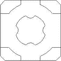
[0014] Low-profile multi-purpose ferrite core is made of soft ferrite into the shape as shown in the figure. The bottom surface or bottom plate is square or rectangular, with a cylinder 1 at the center, and four lead slots 2 on the outer edge of the cylinder to facilitate the connection of multilayer PCB windings. On the four corners of the square or rectangle are respectively side legs 3 with a nearly polyhedral cross-sectional shape. The shapes of these side legs are irregular, but they do not affect the function and effect of the magnetic core of the present invention.

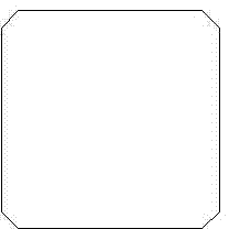
[0015] The above parts cooperate with a square or rectangular magnetic sheet of the same size or with a part of the same shape and size to form a magnetic core with a closed magnetic circuit. There is an air gap or no air gap at the fit of the central cylinder. If there is an air gap, the size of the air gap is 0.01mm to 2mm.

[0016] The thickness of the bottom plate and the paired magnetic sheet is 0.4mm...


PUM

PropertyMeasurementUnit
heightaaaaaaaaaa
lengthaaaaaaaaaa
thicknessaaaaaaaaaa

Abstract

The invention provides a multi-functional ferrite core which is characterized in that one bottom surface of the multi-functional ferrite core is square or rectangular; the center part of the bottom surface is provided with a cylinder; four wire leading slots which facilitate the wiring of multiple layers of PCB (printed circuit board) windings are arranged at the periphery of the cylinder; four square or rectangular corners are respectively provided with an edge leg in a shape similar to a polyhedron cross section, and respectively matched with an square or rectangular magnetic sheet which has a same size with the corners or matched with a magnetic core which has a same shape and size with the corners, thus forming a low magnetic core capable of being provided with a multi-winding transformer; and air gaps or no air gaps exist between the cylinder of the magnetic core and the magnetic sheets or between the cylinders. The multi-functional ferrite core provided by the invention has the advantages that the magnetic shield and heat dissipation characteristics are better considered, and high power density, a multiplexed output function and multifunction can be realized.

Description

technical field [0001] The invention relates to a soft ferrite core, in particular to a low profile multipurpose ferrite core. Background technique [0002] 1) The common ferrite cores used for miniaturized switching power supplies or DC-DC converter transformers are large in size and high in installation height, and it is difficult to balance the convenience of multi-winding outlets, heat dissipation performance and magnetic shielding. Contradictions, cannot well adapt to the current development trend of electronic products miniaturization, thinning, high power density and good electromagnetic compatibility; [0003] 2) The existing low-profile EE, EI, and ER magnetic cores are the most commonly used shapes, but they can only be routed from both sides, which is not very convenient for multi-winding and multi-output designs; due to the large openings on both sides, there are many The winding "overflow", the magnetic shielding effect is not ideal, and it is easy to generate ...

Claims


Application Information

Patent Timeline
Patent Type & Authority Applications(China)
IPC IPC(8): H01F27/24H01F41/02
Inventor 赵光陈冉商燕彬李庆年永全王华妹
Owner NANJING NEW CONDA MAGNETIC INDAL
Why Eureka
Try Eureka