
Water cooling plate unit applied to battery pack

A technology of water-cooled plates and battery packs, which is applied to electrical components, secondary batteries, battery temperature control, etc., and can solve problems such as increased manufacturing costs, high manufacturing costs, and excessive volume of the battery pack 2

Active Publication Date: 2013-10-23
ASIA VITAL COMPONENTS SHENZHEN CO LTD
View PDF4 Cites 20 Cited by
  • Summary
  • Abstract
  • Description
  • Claims
  • Application Information

AI Technical Summary

Problems solved by technology

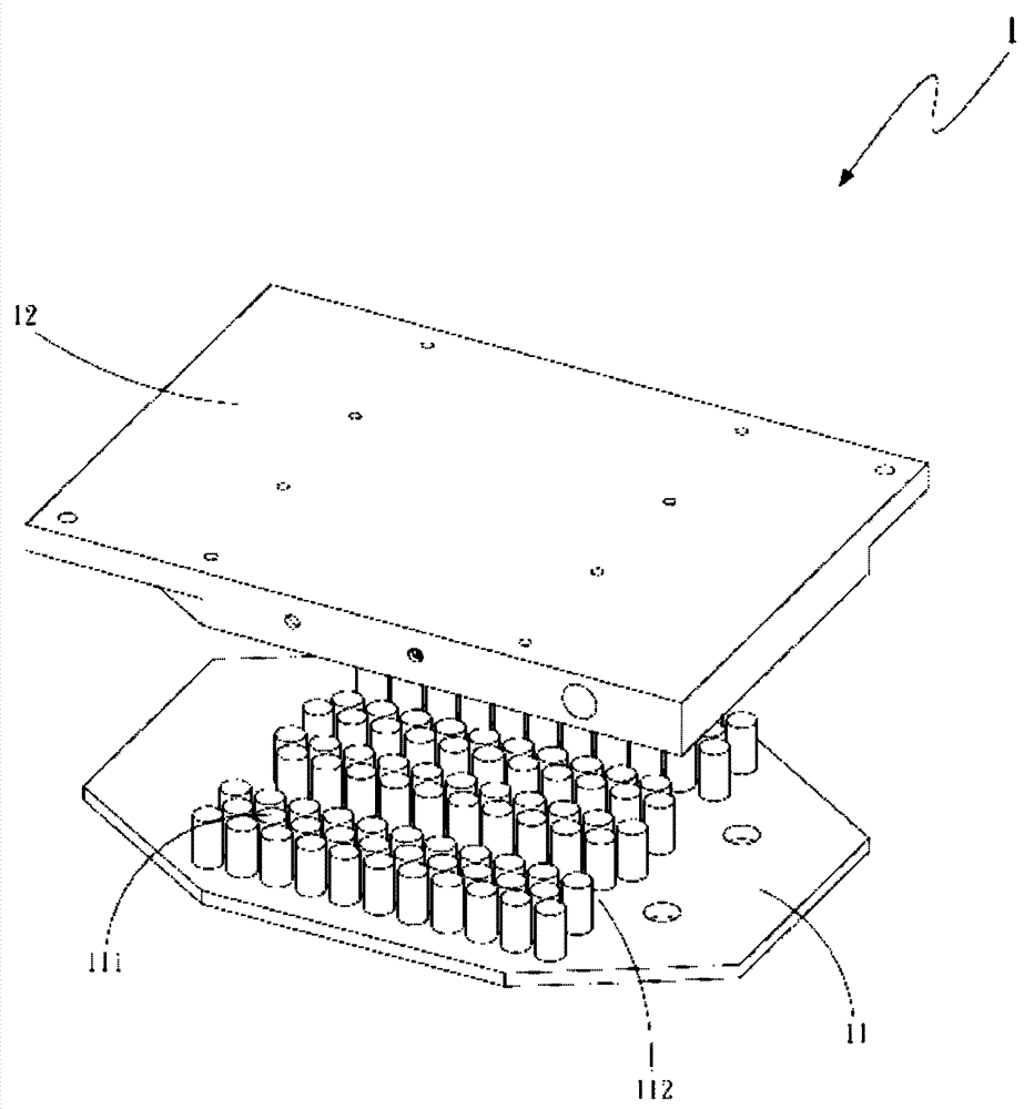
[0005] The cover plate 12 also needs to be formed by CNC machining or gravity casting into a shape that can cover the separation column 111 and the base 11. Therefore, it is also necessary to use a thick plate body to complete the processing, so the water-cooled plate unit 1 The minimum thickness of the forming is 20MM, so the problem of excessive thickness and weight is caused, and the manufacturing cost of the product is high
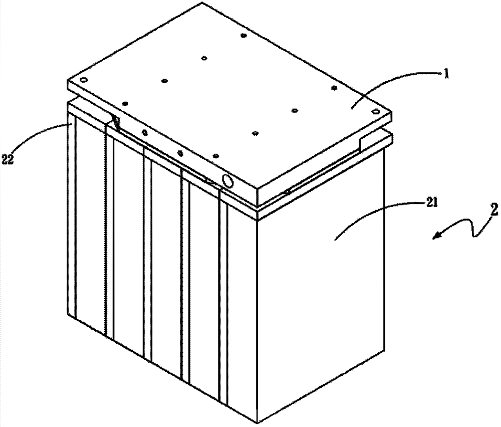
[0006] see again Figure 1B As shown, the battery pack 2 has a plurality of batteries 21, but because the thickness of the water-cooled plate unit 1 is too thick, if it is interspersed between the batteries 21, the volume of the battery pack 2 will be too large, so the water-cooled plate unit 1 cannot Installed and interspersed between the batteries 21, the instrument can intersperse the aluminum sheets 22 between the batteries 21 and attach the batteries 21, and then attach the end edges of the aluminum sheets 22 through the water-cooled plate unit 1, so that the batteries 21 The heat generated is indirectly transferred to the water-cooled plate unit 1 through the aluminum sheet 22 attached to the surface of the battery 21, and then the heat is taken away by the water-cooled plate unit 1 to complete the purpose of heat dissipation. Efficiency is poor, and needs to utilize aluminum flake 22 to carry out heat dissipation and its whole manufacturing cost improves relatively; Therefore known technology has following shortcoming:
[0007] 1. The thickness is too thick and the weight is too heavy;
[0008] 2. High manufacturing cost;
[0009] 3. Poor cooling efficiency

Method used


Image

  • Water cooling plate unit applied to battery pack
  • Water cooling plate unit applied to battery pack
  • Water cooling plate unit applied to battery pack

Examples


Embodiment Construction

[0045] The above-mentioned purpose of the present invention and its structural and functional characteristics will be described according to the preferred embodiments of the accompanying drawings.

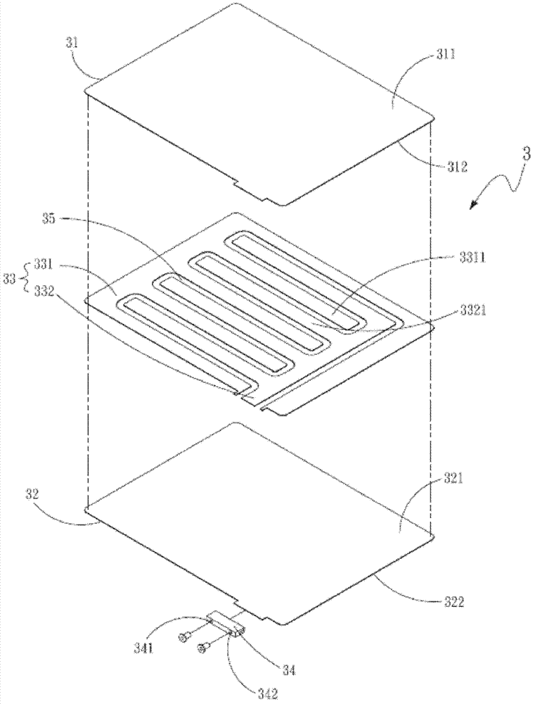
[0046] see figure 2 and image 3 As shown, it is a three-dimensional exploded view and a three-dimensional assembly view of the first preferred embodiment of the water-cooled plate unit applied to the battery pack of the present invention. As shown in the figure, the water-cooled plate unit 3 includes a first plate body 31 and a first plate body 31. Two plates 32, a channel structure 33 and a joint group 34, the two sides of the first plate 31 are respectively formed with a first side 311 and a second side 312, and the two sides of the second plate 32 are respectively formed with a first side Three sides 321 and a fourth side 322 , wherein the surface of the third side 321 is correspondingly covered with the surface of the second side 312 of the first plate body 31 .

[0047] Th...


PUM


Abstract

The invention provides a water cooling plate unit applied to a battery pack. The water cooling plate unit comprises a first plate body, a second plate body and a runner structure, wherein the first plate body and the second plate body are correspondingly covered; the runner structure is formed by a punching process and is provided with a first separation piece and a second separation piece; and the runner structure is arranged between the first plate body and the second plate body to form a channel. Therefore, the runner structure formed by the punching process can realize thinness; materials and the manufacturing cost are saved; and the heat radiation efficiency can be effectively improved when the water cooling plate unit is assembled on the battery pack.

Description

technical field [0001] The invention relates to a water-cooling plate, especially a water-cooling plate unit applied to a battery pack, which can reduce weight and achieve thinning and save material cost. Background technique [0002] In the occasions where it is currently impossible to use household AC or general DC power by wiring at any time, it is necessary to supply power by adding batteries, the most common being vehicles, lamps, power tools, electronic equipment, communication equipment or heat exchange equipment, etc. Both need to use batteries to directly or indirectly supplement the supply of electricity. [0003] During the operation of the battery pack, the battery will undergo a process of charging and discharging. During the charging and discharging process, due to the electrons running in the filling material, the temperature of the battery body will rise, and the temperature will continue to rise and exceed the working range of the battery. Temperature has a...

Claims


Application Information

Patent Timeline
Patent Type & Authority Applications(China)
IPC IPC(8): H01M10/50H01M10/60H01M10/613H01M10/6555H01M10/6557H01M10/6568
CPCY02E60/12H01M10/6568H01M10/6567H01M10/627H01M10/613H01M10/647H01M10/6557Y02E60/10
Inventor 邱子钦
Owner ASIA VITAL COMPONENTS SHENZHEN CO LTD
Learn More