Backlight module group and liquid crystal display device

A technology for backlight modules and display panels, which is applied in the directions of light guides, optics, optical components, etc., can solve the problems of difficulty in achieving thinning and large thickness of backlight modules.

Active Publication Date: 2016-07-20
BOE TECH GRP CO LTD
View PDF9 Cites 21 Cited by
  • Summary
  • Abstract
  • Description
  • Claims
  • Application Information

AI Technical Summary

Problems solved by technology

[0004] The present invention aims at the problem that the thickness of the backlight module in the existing liquid crystal display device is relatively large, so it is difficult to realize thinning, and provides a backlight module and a liquid crystal display device with a small thickness.

Method used


Image

  • Backlight module group and liquid crystal display device
  • Backlight module group and liquid crystal display device
  • Backlight module group and liquid crystal display device

Examples


Embodiment 1

[0033] Such as Figure 2 to Figure 9 As shown, this embodiment provides a liquid crystal display device and a backlight module used therein.

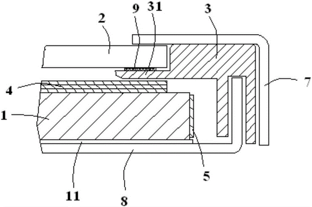
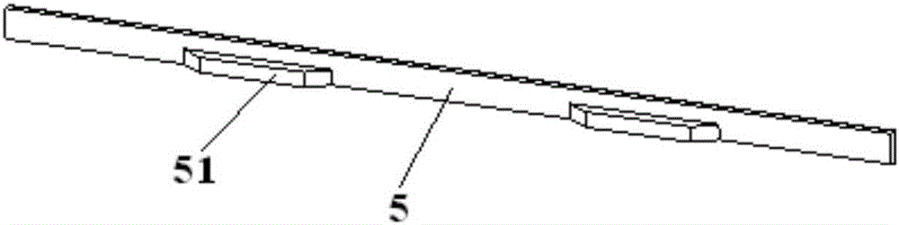
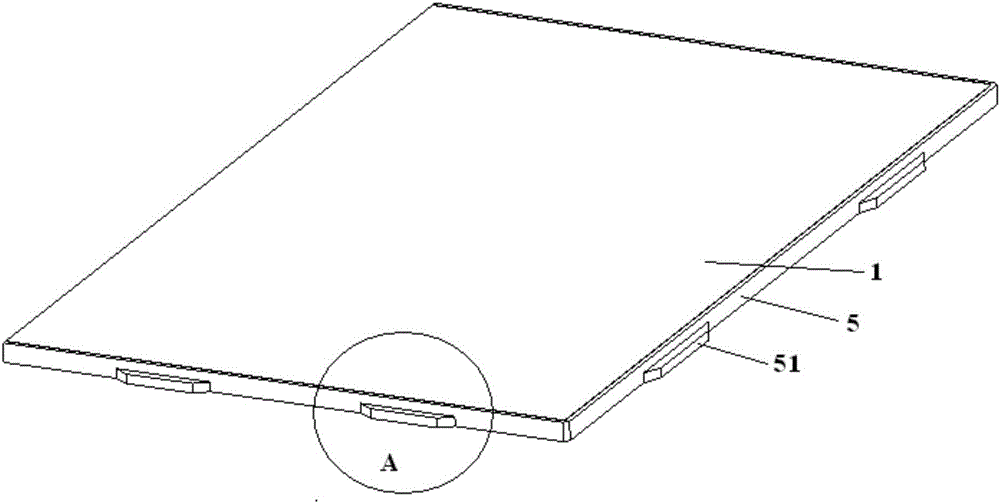
[0034] Specifically, the backlight module of this embodiment includes a light guide plate 1 , a light blocking member 5 , and a plastic frame 3 . in:

[0035] The light guide plate 1 has a bottom surface and a light-emitting surface opposite to each other, and a plurality of sides connected between the bottom surface and the light-emitting surface, and the sides include a light-incident side and a non-light-incident side.

[0036] The light guide plate 1 is generally a rectangular plate. One of the two large surfaces of the rectangular plate is the bottom surface for light reflection, and a reflective sheet 11 may be provided outside it, while the other surface is a light-emitting surface for light emission. The bottom surface and the light-emitting surface are connected by multiple sides, at least one of which needs to be provided wi...


PUM


Abstract

The invention provides a backlight module group and a liquid crystal display device, and belongs to the technical field of liquid crystal display, and can solve problems that the thickness of a backlight module in a conventional liquid crystal display device is larger, and the backlight module in the conventional liquid crystal display device cannot be thin. The backlight module group comprises a light guide plate, and the light guide plate is provided with a bottom surface and a light outgoing surface, wherein the bottom surface and the light outgoing surface are opposite to each other. The light guide plate is also provided with a plurality of side surfaces which are connected between the bottom surface and the light outgoing surface, and the side surfaces comprise a light incoming side surface and a non-light-incoming side surface. The backlight module group also comprises a light blocking part which is disposed outside the non-light-incoming side surface, contacts with the non-light-incoming side surface and is fixedly arranged relative to the light guide plate. A side, far from the non-light-incoming side surface of the light guide plate, of the light blocking part is provided with a supporting projection. A side, close to the light-outgoing surface of the light guide plate, of the supporting projection serves as a supporting side. The distance between the supporting side and the bottom surface of the light guide plate is less than the thickness of the light guide plate. The backlight module group also comprises a glue frame, and the glue frame comprises an isolation pad part which is disposed at the supporting side of the supporting projection of the light blocking part.

Description

technical field [0001] The invention belongs to the technical field of liquid crystal display, and in particular relates to a backlight module and a liquid crystal display device. Background technique [0002] Such as figure 1 As shown, the existing liquid crystal display device mainly includes a backlight module, a display panel 2, a bezel 7 and the like. In the backlight module, the light guide plate 1, the reflection sheet 11, the optical film layer 4, etc. are set in the back plate 8, the plastic frame 3 is connected to the back plate 8, and the plastic frame 3 has a Film layer 4) The spacer part 31 on the light-emitting surface. When the backlight module, the display panel 2, the surface frame 7, etc. are composed of a liquid crystal display device, the spacer part 31 is sandwiched between the edge of the display panel 2 and the light guide plate 1. Between, and through the double-sided adhesive tape 9 and display panel 2 bonding, so as to play the role of fixing the ...

Claims


Application Information

Patent Timeline
Patent Type & Authority Applications(China)
IPC IPC(8): G02B6/00G02F1/13357
CPCG02B6/0088G02F1/133606G02F1/133608G02F1/133607G02F1/13332G02F1/133314G02F1/133317G02B6/0055G02B6/0065G02B6/0093G02F1/133308
Inventor 吴忠宝
Owner BOE TECH GRP CO LTD
Why Eureka
Try Eureka