Battery cap assembly

A battery cover and assembly technology, applied in battery pack parts, electrical components, circuits, etc., can solve problems such as reduced assembly performance, increased number of assembly parts, and increased cost

Inactive Publication Date: 2002-12-18
ALPS ALPINE CO LTD
View PDF0 Cites 19 Cited by
  • Summary
  • Abstract
  • Description
  • Claims
  • Application Information

AI Technical Summary

Problems solved by technology

In addition, the structure is to paste the insulating sheet 55 and connect the protective device 56 with the lead wires 54 and 57, so

Method used


Image

  • Battery cap assembly
  • Battery cap assembly
  • Battery cap assembly

Examples


Embodiment approach

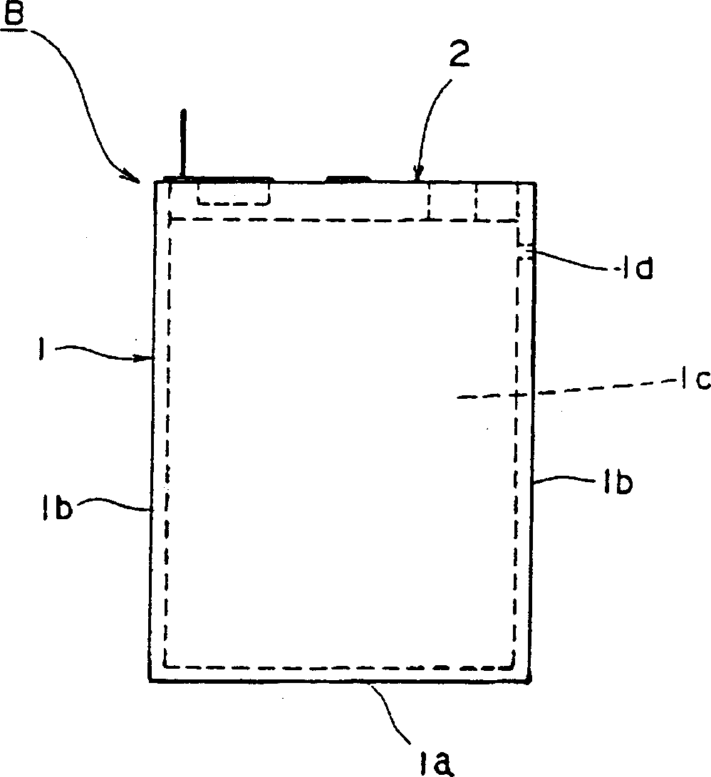
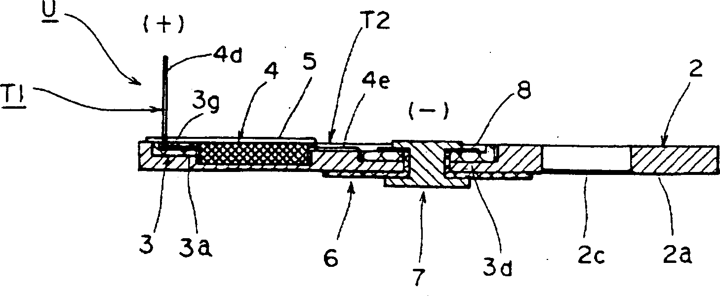
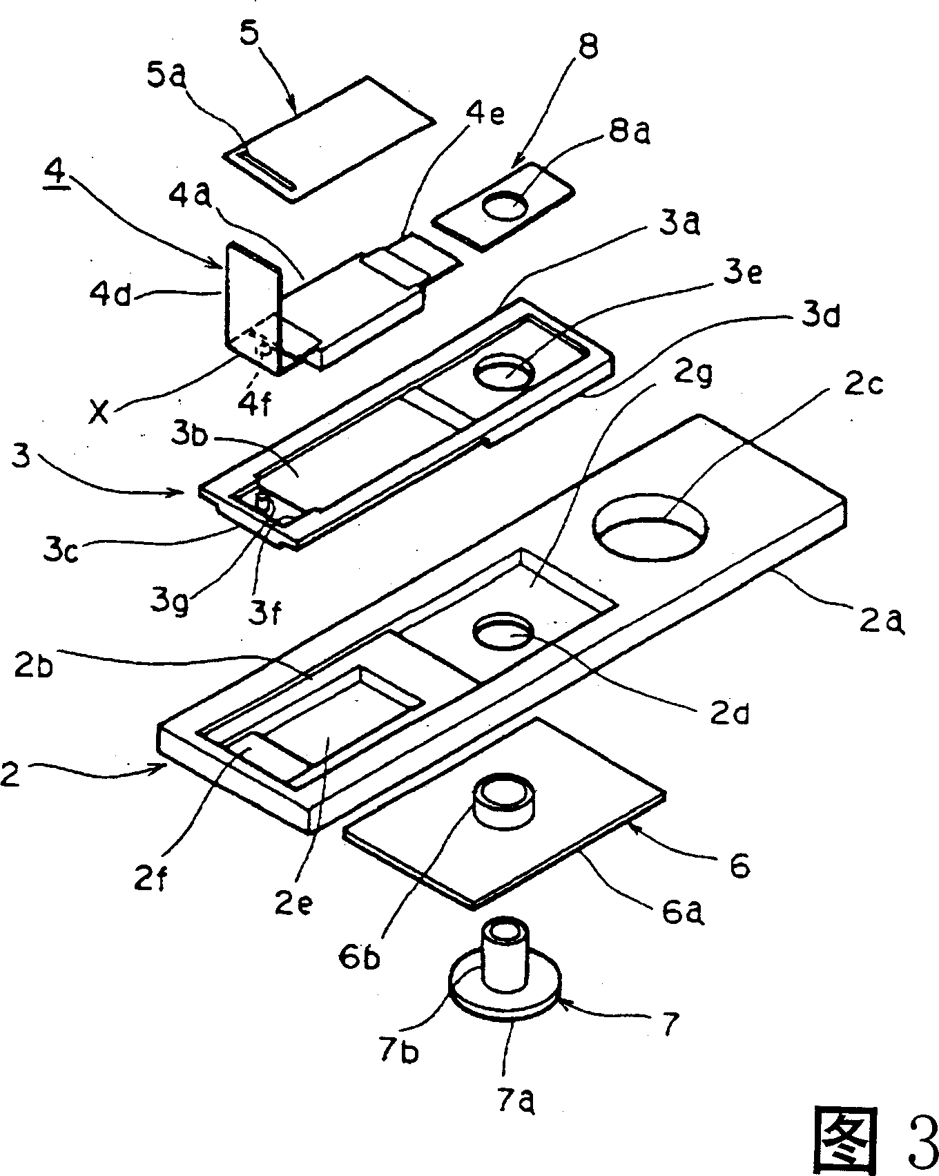
[0047] The battery cover assembly will be described in detail below according to the accompanying drawings. figure 1 It is a front view of a battery mounted with the battery cover assembly of the present invention. figure 2 It is a sectional view of main parts of the first embodiment U of the battery cover assembly of the present invention. Fig. 3 is an exploded perspective view of main parts of the first embodiment U of the battery cover assembly of the present invention. Figure 4 It is a side view of the protection device according to the first embodiment U of the battery cover assembly of the present invention. Figure 5 It is a cross-sectional view of main parts showing a state where the terminal portion of the protective device according to the first embodiment of the battery cover assembly of the present invention is attached.

[0048] The battery cover assembly of the present invention is as figure 1 As shown, it is used to seal the battery cell 1 of an organic b...


PUM


Abstract

PURPOSE: To provide a battery cap unit which prevents degradation of accuracy of a protection unit by using a heat sensitive switch as one and can constitute a compact, fit for assembly, and low-cost battery by integrating and unitizing the protection unit with a battery cap body. CONSTITUTION: The unit is provided with a metal battery cap body 2 sealing a battery cell 1 used for a secondary battery and shielding the inside of the cell, and a heat sensitive switch 4 making changeover of switching at a given temperature, and it is so structured that the heat sensitive switch 4 is fitted to the battery cap body 2 and the heat sensitive switch 4 and the battery cap body 2 are integrated, to aim at unitization.

Description

technical field [0001] The present invention relates to a structure of a battery cover assembly for sealing a battery unit, which is mainly used in chargeable and dischargeable lithium ion storage batteries (secondary batteries) of mobile electronic equipment such as cameras, notebook computers, and mobile phones. Background technique [0002] Drawings of conventional batteries will be described. Figure 11 It is the front view of the conventional battery. [0003] The battery unit 51 is made of an aluminum frame, and has a rectangular bottom wall 51a and a side wall 51b extending upward from the bottom wall 51a. Inside 51c is put into the electrode group that is not shown in the figure by positive plate, negative plate and the diaphragm that is arranged between this positive plate, negative plate; elements of the electrolyte. The electrolyte is made by dissolving lithium salt in an organic solvent. [0004] The battery cover 52 has an aluminum plate-shaped member 52a and...

Claims


Application Information

Patent Timeline
IPC IPC(8): H01M2/04H01M2/10H01M2/12H01M2/30H01M2/34
CPCY02E60/10
Inventor 畦间忠满玉城伸一
Owner ALPS ALPINE CO LTD
Why Eureka
Try Eureka