Toy gun mechanism with a sliding bolt assembly

a technology of sliding bolts and toy guns, which is applied in the direction of toy guns, compressed gas guns, white arms/cold weapons, etc., can solve the problems that the realistic appearance of toy guns cannot satisfy serious collectors, and achieve the effect of realistic firing of toy guns

Inactive Publication Date: 2010-01-28
LEE YI JUNG +1
View PDF24 Cites 16 Cited by
  • Summary
  • Abstract
  • Description
  • Claims
  • Application Information

AI Technical Summary

Benefits of technology

[0011]The objective of the present invention is to make a toy gun's appearance more realistic when fired.

Problems solved by technology

Accordingly, toy guns are not realistic enough to satisfy serious collectors.

Method used


Image

  • Toy gun mechanism with a sliding bolt assembly
  • Toy gun mechanism with a sliding bolt assembly
  • Toy gun mechanism with a sliding bolt assembly

Examples


Embodiment Construction

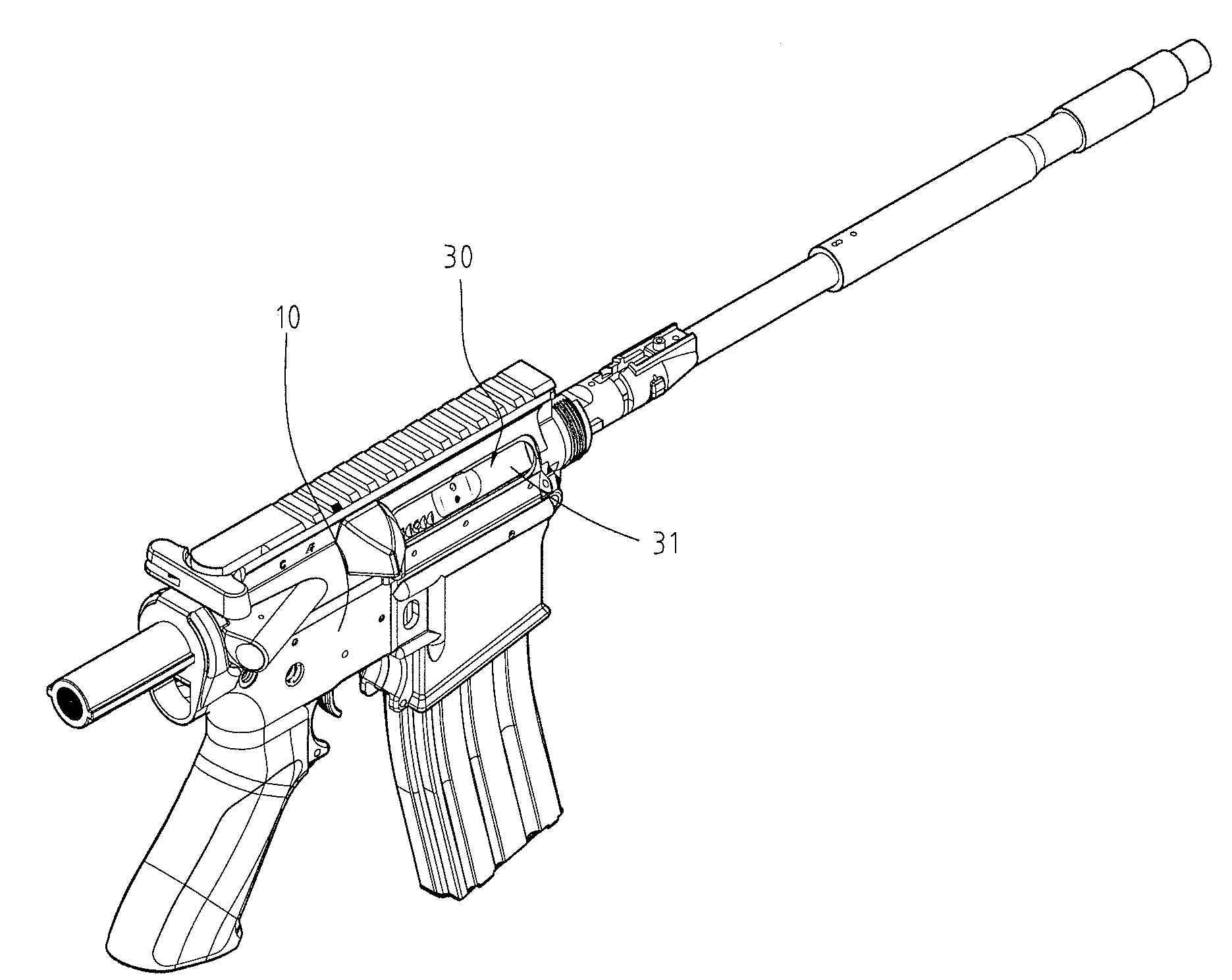
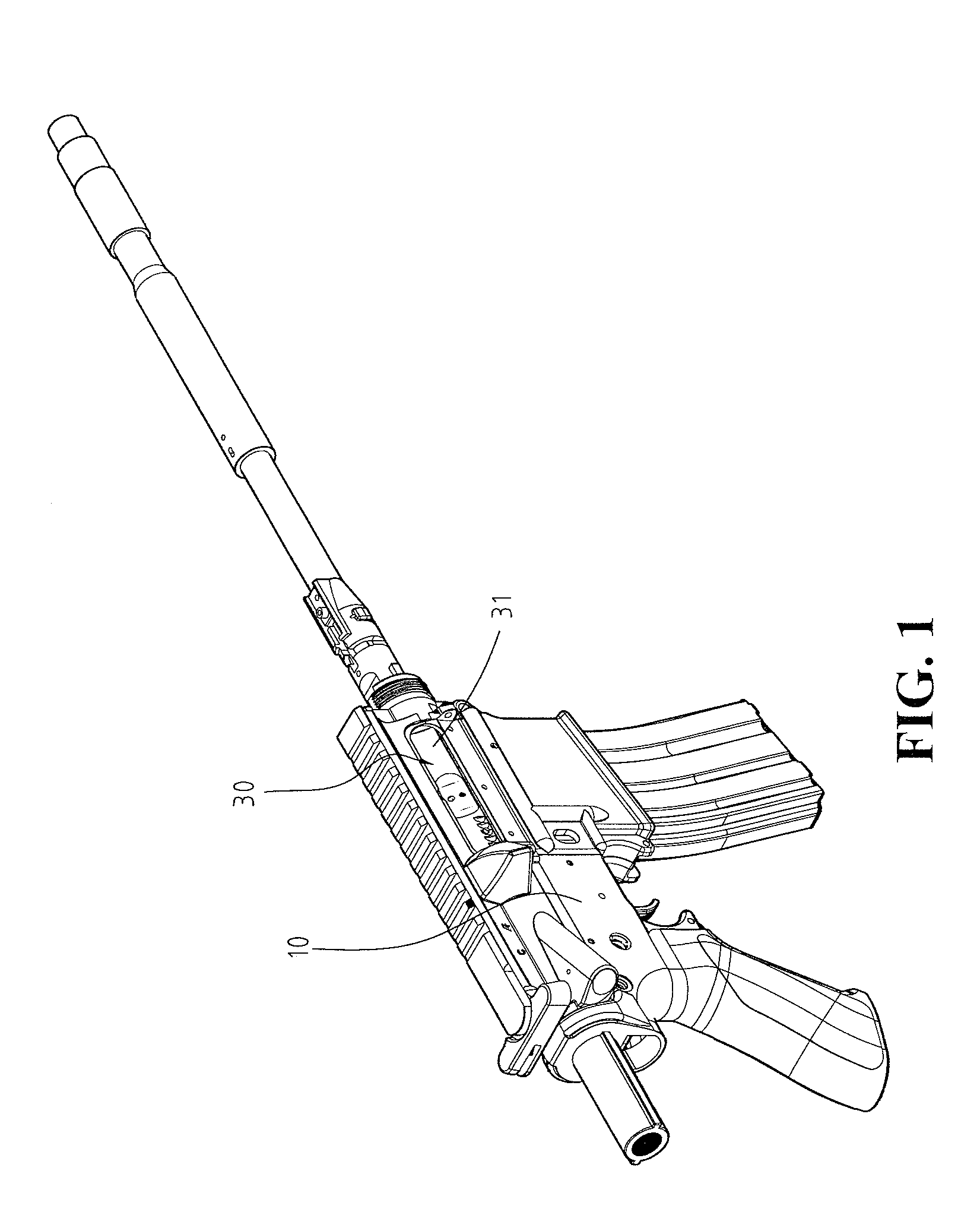
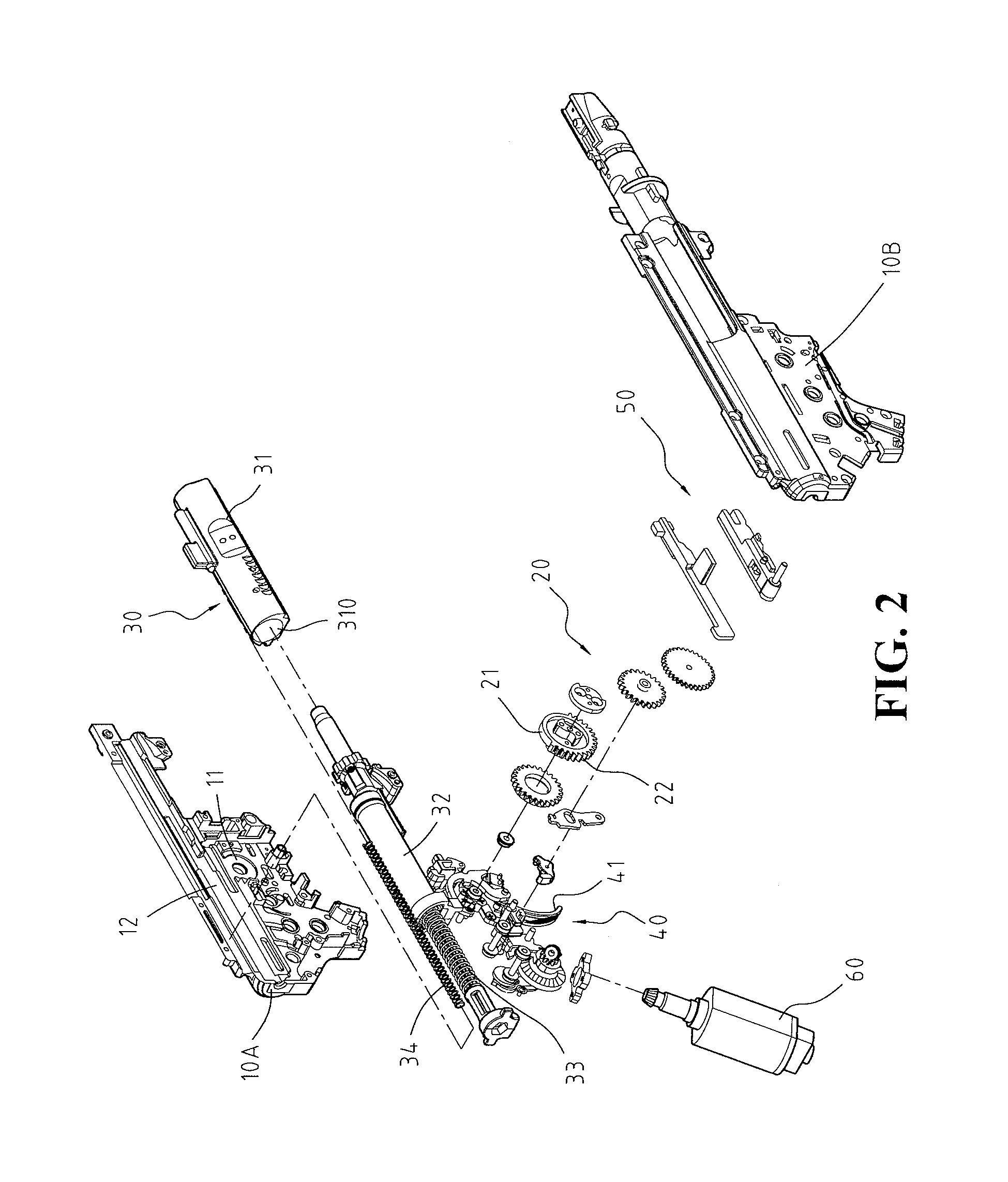
[0022]With reference to FIGS. 1, 2, 3 and 8, a toy gun mechanism in accordance with the present invention comprises a housing (10), a motor (60), a gear assembly (20), a bolt assembly (30), a trigger assembly (40) and a latch (50).

[0023]The housing (10) has a top, a bottom, a front end and an opening and comprises two shells (10A, 10B), a gear chamber (11) and a bolt chamber (12). The opening is formed longitudinally through the front end near the top of the housing (10).

[0024]The shells (10A, 10B) connect to each other to form the housing (10).

[0025]The gear chamber (11) is formed inside the housing (10) along the bottom.

[0026]The bolt chamber (12) is formed longitudinally inside the housing (10) between the shells (10A, 10B) and communicates with the gear chamber (11) and the opening in the front end of the housing (10).

[0027]The motor (60) has a drive shaft. The drive shaft protrudes into the gear chamber (11).

[0028]The gear assembly (20) is mounted in the gear chamber (11), is d...


PUM


Abstract

The present invention relates to a toy gun mechanism with a sliding bolt assembly that closely resembles a real gun when the toy gun is fired and comprises a housing, a motor, a gear assembly, a bolt assembly, a trigger assembly and a latch. The gear assembly is mounted in the housing and is connected to and driven by the motor. The bolt assembly is mounted slidably in the housing and is selectively moved to a cocked position by the gear assembly. The trigger assembly releases the bolt assembly and drives air from the bolt assembly as the bolt assembly moves forward.

Description

FIELD OF THE INVENTION[0001]The present invention relates to toy gun mechanism and more particularly, to a toy gun with a sliding bolt assembly that moves back and forth when the toy gun is fired to imitate a real gun.BACKGROUND OF THE INVENTION[0002]In many countries, ownership of guns is controlled and regulated by government laws. Under strict gun control, private citizens can only own toy guns.[0003]Most toy guns currently available that shoot toy bullets use either compressed gas cylinders or powerful springs to shoot the toy bullets.[0004]Such a toy gun is shown in Arms Magazine, Vol. 12, pp. 33, 2007, and uses a powerful spring to shoot bullets. The toy gun comprises a motor, a housing, a gear assembly and a piston assembly.[0005]The gear assembly is mounted in the housing and is connected to and rotated by the motor.[0006]The piston assembly is mounted in the housing, is connected to the gear assembly and comprises a piston sleeve, a piston rod and a powerful spring.[0007]Th...

Claims


Application Information

Patent Timeline
Patent Type & Authority Applications(United States)
IPC IPC(8): A63H31/08A63H33/30
CPCF41B11/646H03G3/30H03G3/001
Inventor LEE, YI-JUNGCHENG, LI-TE
Owner LEE YI JUNG
Why Eureka
Try Eureka