Micro-channel heat exchanger

a heat exchanger and micro-channel technology, applied in indirect heat exchangers, refrigeration components, lighting and heating apparatus, etc., can solve the problems of reducing work efficiency, difficult installation of micro-channel heat exchangers and design of packing cases, and unstable operation of refrigeration systems

Active Publication Date: 2010-10-07
SANHUA HANGZHOU MICRO CHANNEL HEAT EXCHANGER
View PDF14 Cites 16 Cited by
  • Summary
  • Abstract
  • Description
  • Claims
  • Application Information

AI Technical Summary

Benefits of technology

[0012]The above summary of the present invention is not intended to describe each disclosed embodiment or every implementation ...

Problems solved by technology

The location of the outlet of the micro-channel heat exchanger having an odd number of flow paths is different from that of the outlet of the micro-channel heat exchanger having an even number of flow paths, which makes the installation of the micro-channel heat exchanger and design of the packing case therefore difficult.
The conventional micro-c...

Method used


Image

  • Micro-channel heat exchanger
  • Micro-channel heat exchanger
  • Micro-channel heat exchanger

Examples


Embodiment Construction

[0024]Reference will be made in detail to embodiments of the present invention. The embodiments described herein with reference to drawings are explanatory, illustrative, and used to generally understand the present invention. The embodiments shall not be construed to limit the present invention. The same or similar elements and the elements having same or similar functions are denoted by like reference numerals throughout the descriptions.

[0025]In the description, terms such as “first”, “second” are used for convenience of description and cannot be constructed to limit the present invention.

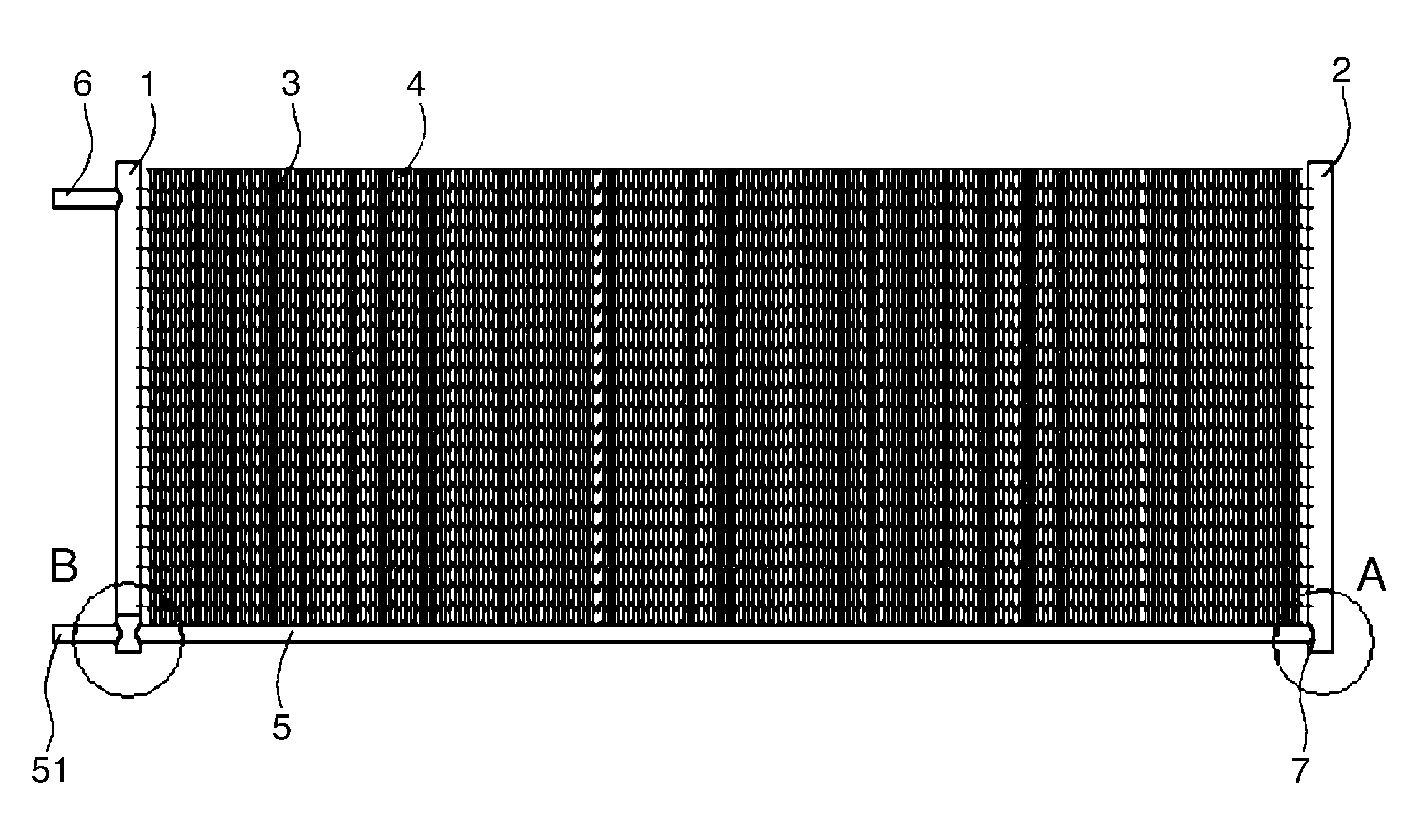
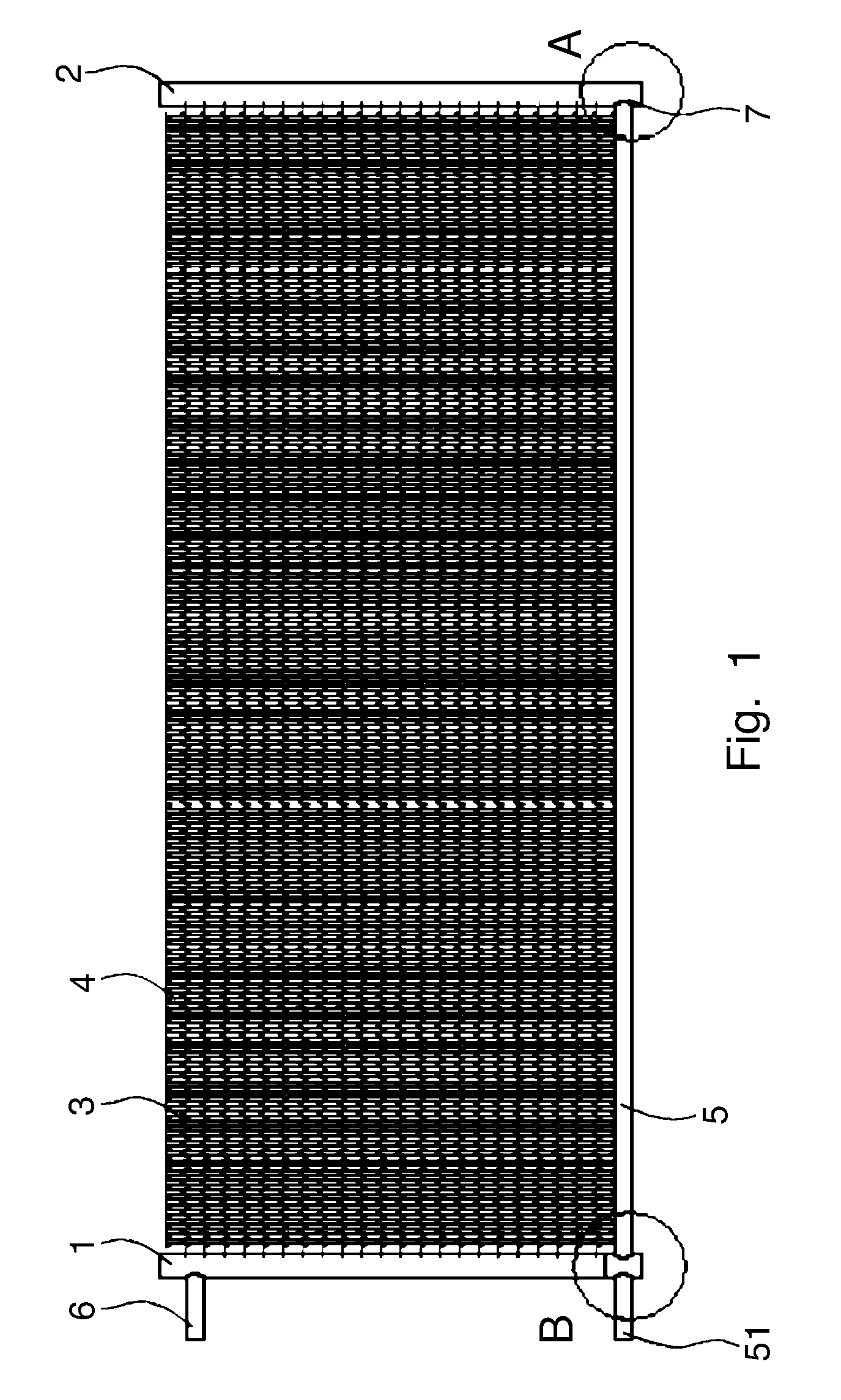
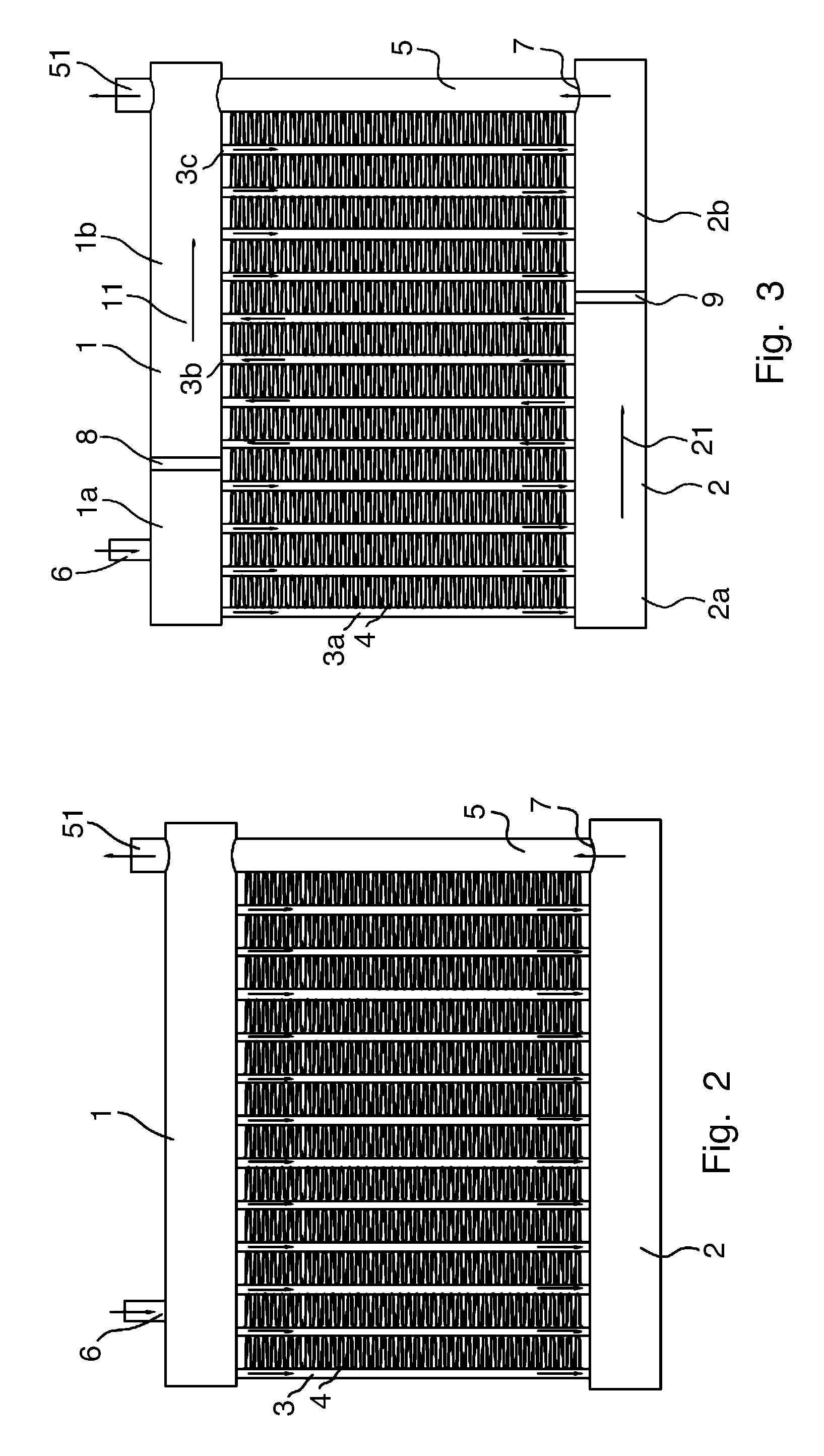
[0026]As shown in FIGS. 1 and 2, the micro-channel heat exchanger according to an embodiment of the present invention comprises a first header 1, a second header 2, flat tubes 3, fins 4 and a return pipe 5.

[0027]In FIG. 1, the first header 1 is located at the left side and the second header 2 is located at the right side. In FIG. 2, the first header 1 is located at the upper side and the second ...


PUM


Abstract

There is disclosed a micro-channel heat exchanger, comprising a first header formed with an inlet; a second header spaced apart from the first header, one of the first and second headers being formed with an outlet; flat tubes, two ends of each flat tube being connected with the first and second headers respectively such that a plurality of micro-channels of each flat tube communicate with the first and second headers; fins, each fin being disposed between two adjacent flat tubes; and a return pipe, a first end of which being connected to the outlet formed in one of the first and second headers and a second end thereof being extended towards the other of the first and second headers. The location of the outlet of the micro-channel heat exchanger is easy to change, and the micro-channel heat exchanger is low in cost, compact in structure and easy to install.

Description

CROSS REFERENCE TO RELATED APPLICATIONS[0001]This application is entitled to the benefit of and incorporates by reference essential subject matter disclosed in Chinese Patent Application No. 200910132690.5 filed on Apr. 7, 2009.BACKGROUND OF THE INVENTION[0002]1. Field of the Invention[0003]The present invention generally relates to a heat exchanger, more particularly, to a micro-channel heat exchanger.[0004]2. Description of the Related Art[0005]The micro-channel heat exchanger is used for heat exchanging. For example the micro-channel heat exchanger may be used as a condenser or an evaporator in a refrigeration system and generally comprises headers, flat tubes formed with micro channels, and fins disposed between two adjacent flat tubes. The micro-channel heat exchanger may comprise a plurality of flow paths, when the number of the flow paths is even, the outlet and inlet of the micro-channel heat exchanger are formed in the same header, and when the number of the flow paths is o...

Claims


Application Information

Patent Timeline
IPC IPC(8): F28F9/02
CPCF28D1/05391F28F9/0246F28F9/16F25B39/04F28F2260/02F28F2275/06F25B2339/044F28D2021/007F28D2021/0071F28F9/0209
Inventor XIANGXUN, LUHUANG, LIN-JIE
Owner SANHUA HANGZHOU MICRO CHANNEL HEAT EXCHANGER
Why Eureka
Try Eureka