Release agent delivery system for use in printer devices

a technology of printer devices and release agents, which is applied in the direction of electrographic process devices, instruments, optics, etc., can solve the problems of low sharpness and quality of immediate printing, unsatisfactory printing page non-uniformity, and certain image or print quality issues with presently used textile materials, so as to improve the uniformity of release agents and reduce non-uniform printing pages. , the effect of finer topographical surfaces

Inactive Publication Date: 2002-09-10
BMP AMERICA
View PDF8 Cites 18 Cited by
  • Summary
  • Abstract
  • Description
  • Claims
  • Application Information

AI Technical Summary

Benefits of technology

Still another object of the present invention is to provide a release agent delivery web which will reduce non-uniform finishes on printed pages.
Yet a further object of the present invention is to provide a release agent delivery system which yields a finer, more uniform circumferential release agent pattern on the fuser roller of an electrophotographic printer.
In accordance with the present invention, the release agent is delivered to the fuser roller by a non-woven thermally bonded textile web of essentially sub-denier fibers. These sub-denier fibers provide much improved uniformity of the release agent delivered to the surface of the fuser roller. Instead of alternating visible areas of matte and glossy finish on the print, the deliver of the release agent by the non-woven essentially sub-denier finish textile web in accordance with the present invention results in a much more uniform pattern of release agent delivery to the fuser roller. This more uniform release agent delivery pattern results in a much more uniform finish of the resultant print.
The sub-denier fibers of the non-woven textile web used in the present invention provide a textile with a finer topographical surface. The textile's surface drags on the fuser roll surface in an oil filled environment. The textile's finer topographical surface yields a finer circumferential oil pattern, or a pattern with a thinner band width, on the fuser roll surface. As the toner is being fused onto the page, the oil residing on the fuser roller is absorbed into the page. The textile web used in the present invention allows for a much finer pattern of oil, with a much thinner band width, to be absorbed into the page.
Finer width and thus more uniform oil patterns absorbed into the printed page dramatically increase the printed image quality by decreasing the individual bar width of the alternating gloss / matte / gloss / matte regions on the printed page. The decrease in size of the individual bar widths of alternating gloss / matte / gloss / matte regions leads to a more integrated appearance on the printed page. The effects of the present invention are most visibly noticeable in full color prints. These improvements are especially important in the ever quickening race toward achieving traditional photographic or silver halide quality in an electrophotographic print.
In attaining these objectives the present invention utilizes, in one embodiment, a textile web of substantially sub-denier fibers with the web weighing in the range of 10 to 150 grams / square meter and being comprised of greater than 50% fibers which are sub-denier in size. The textile web may be produced by thermal bonding, spun bonding, needle felting, melt blowing, or hydroentanging. The textile is impregnated with release agent which is typically silicone oil to a level of 2.5 to 250 grams / square meter. The resultant release agent delivery system provides greatly improved print quality as a result of the significantly improved uniformity of the toner release agent flow pattern applied to the fuser roller. The present invention is a substantial advance in the art.

Problems solved by technology

One drawback of these prior art fuser systems is that since the toner particles are tackified by heat, part of the particles forming the image carried on the paper are often retained by the heated fuser roller rather than penetrating the paper's surface.
Offsetting is an undesirable occurrence which lowers the sharpness and quality of the immediate print as well as contaminating the following prints with toner.
Certain image or print quality issues still exist with the presently used textile materials.
These non-uniformity finishes are very undesirable in printed pages.
As these non-uniform finish areas become smaller, they become more difficult to notice.

Method used


Image

  • Release agent delivery system for use in printer devices
  • Release agent delivery system for use in printer devices
  • Release agent delivery system for use in printer devices

Examples


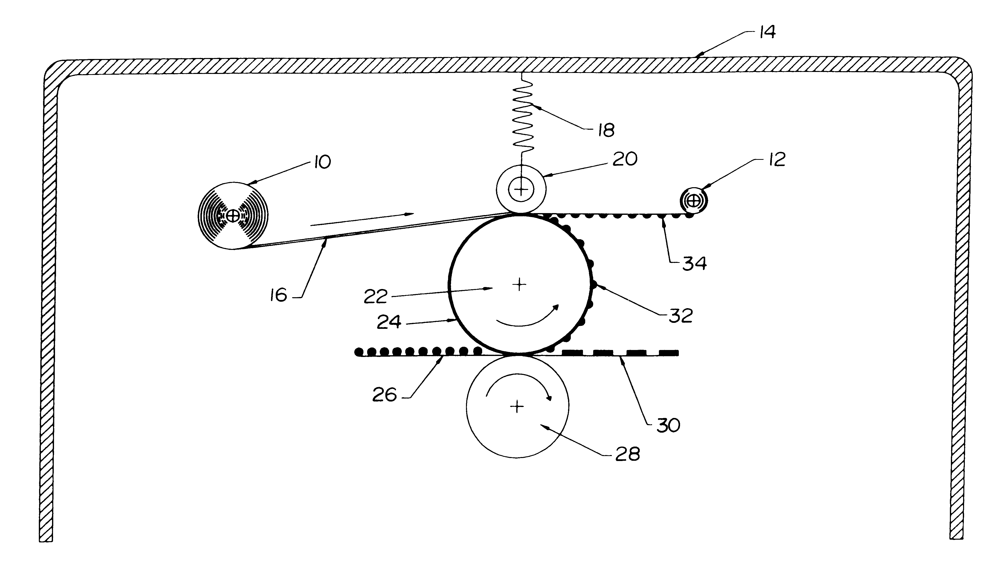
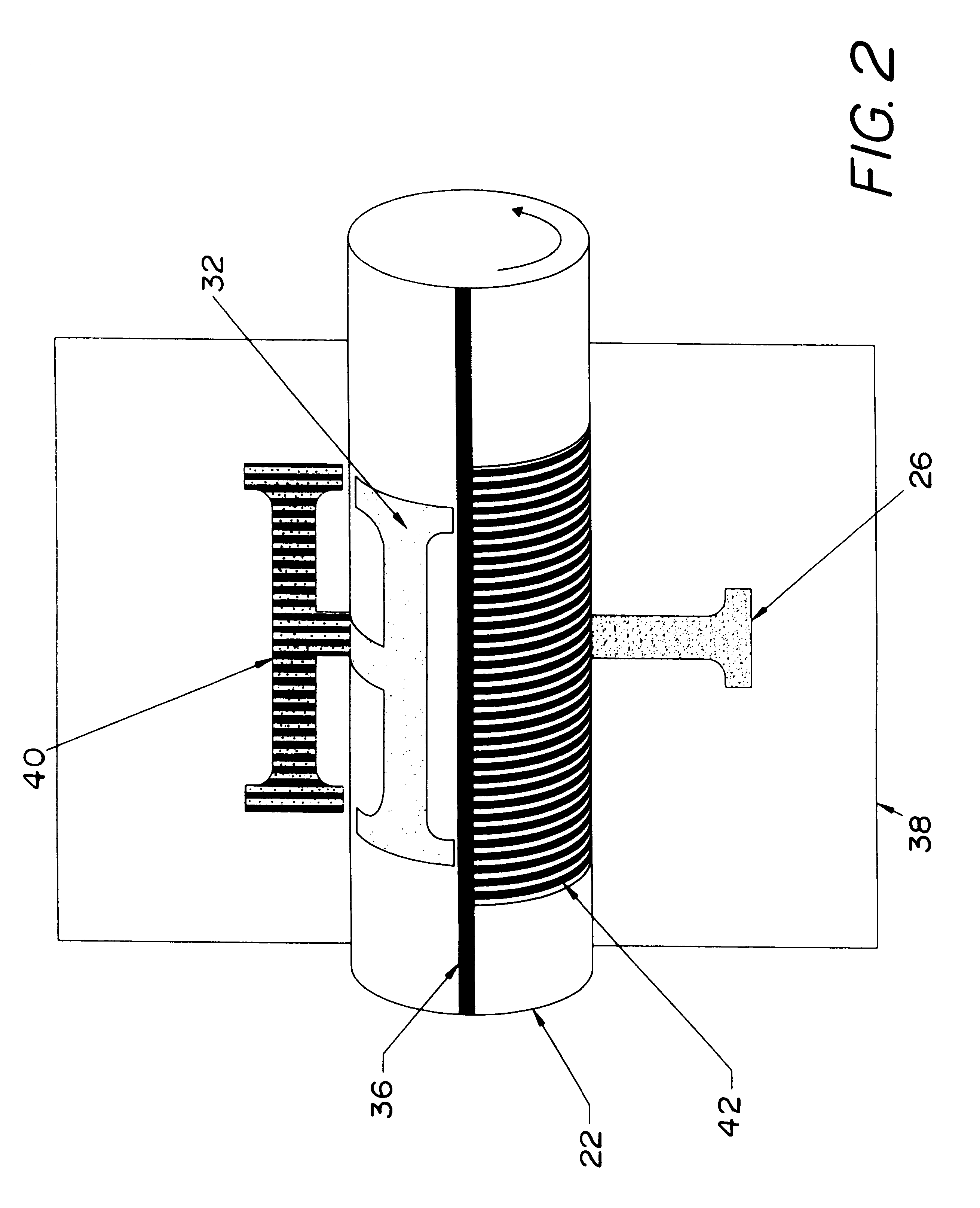
Embodiment Construction

1) A thermal bonded textile was manufactured using 80% 0.7 denier Polyester fiber and 20% 0.8 denier Aramid fiber. The web was manufactured to an area weight of 24 grams / square meter with a thickness of 0.063 mm. The material was then slit to a width of 222 mm The dry slit web was then impregnated with 17 grams / square meter of 1000 Centistoke viscosity silicone oil as manufactured by Dow Corning under the brand name 200 fluid. The impregnated web was then wound onto a metal shaft to a length of 12.34 meters, forming what is known as the supply spool. Another metal shaft was attached to the loose end of the web using pressure sensitive adhesive, forming what is known as the take-up shaft end. Both metal shafts were then inserted into a Tektronix Model Phaser 560 web cartridge and placed into a Model Phaser 560 printer.

To determine the micro-uniformity of oil laydown produced on a electrophotographic print, one common methodology is known as toner dust testing. The toner dust testing ...


PUM


Abstract

A release agent delivery system for an electrophotographic printing process utilizes a web which is a non-woven textile comprised of substantially all sub-denier fibers. The release agent delivery system using the textile produced with predominantly sub-denier fibers, creates finer oil flow patterns which yield improved print quality though decreased microscopic streaking.

Description

The present invention is directed generally to a release agent delivery system for use in an electrophotographic printing process. More particularly, the present invention is directed to the use of a non-woven textile web for use as a release agent delivery device in a release agent delivery system. Most specifically, the present invention is directed to the use of a non-woven thermally bonded textile web of essentially sub-denier fibers in a release agent delivery system. The use of the textile web of sub-denier fibers provides very fine release agent flow patterns that yield highly improved print quality through decreased microscopic streaking of the release agent.DESCRIPTION OF THE PRIOR ARTIn the process of electrostatic printing, a latent electrostatic image is recorded on a photosensitive member with subsequent rendering of the image visible by the application of electrostatic marking particles, typically referred to as toner. The visual image formed by the toner particles is ...

Claims


Application Information

Patent Timeline
Patent Type & Authority Patents(United States)
IPC IPC(8): G03G15/20
CPCG03G15/2025G03G2215/2093
Inventor LEBOLD, ALANPALAZZO, JASONDUGDALE, NEIL GRAHAM
Owner BMP AMERICA
Why Eureka
Try Eureka