Image processing apparatus

Inactive Publication Date: 2010-04-15
OKI DATA CORP
View PDF22 Cites 8 Cited by
  • Summary
  • Abstract
  • Description
  • Claims
  • Application Information

AI Technical Summary

Benefits of technology

[0012]According to the second aspect of the invention, the major color range is determined by assessing whether or not the major color range corresponds to a background. This makes it poss

Problems solved by technology

Document 1, however, does not perform the see-through back image removing process in the dot

Method used


Image

  • Image processing apparatus
  • Image processing apparatus
  • Image processing apparatus

Examples


first embodiment

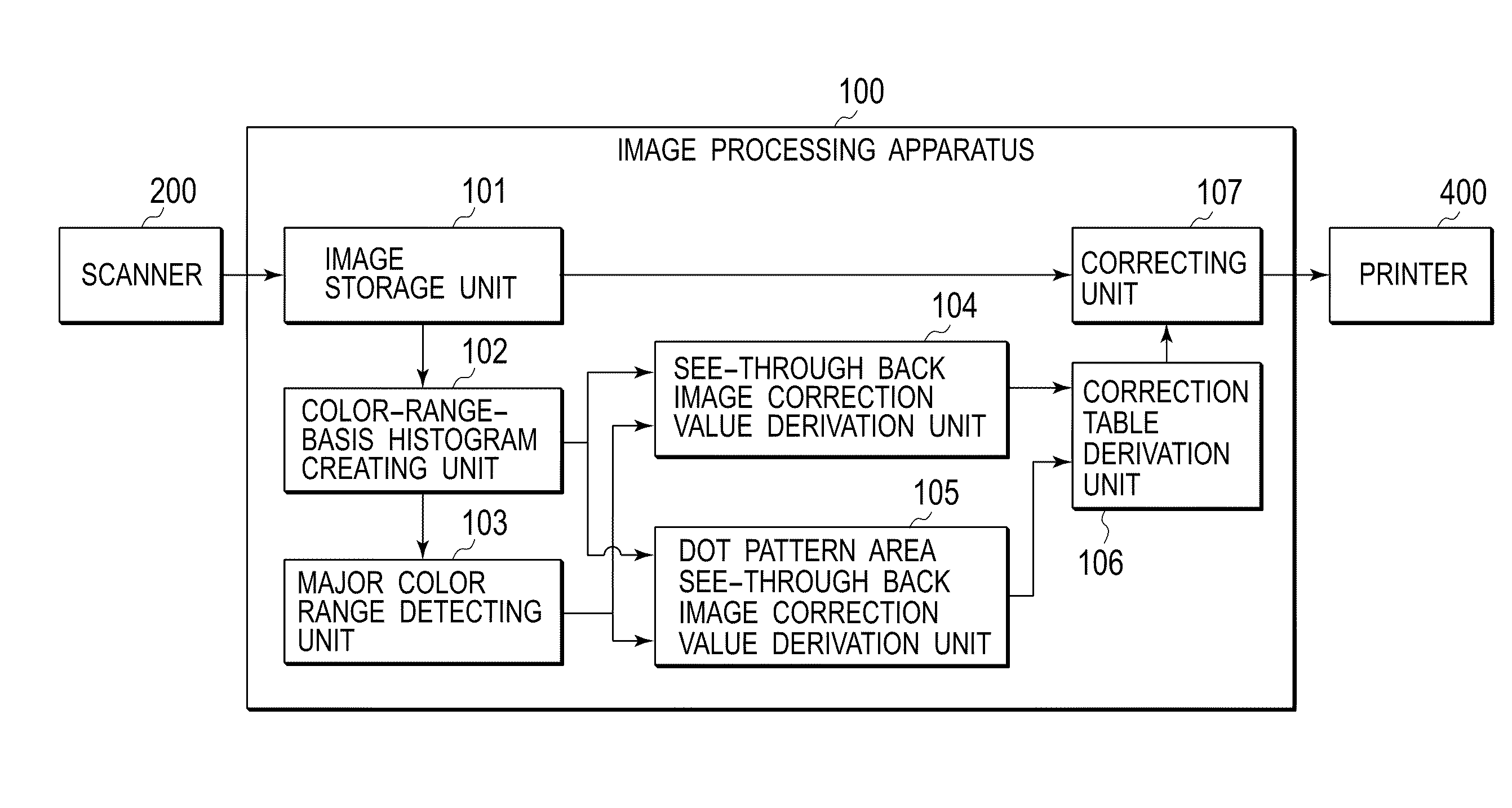
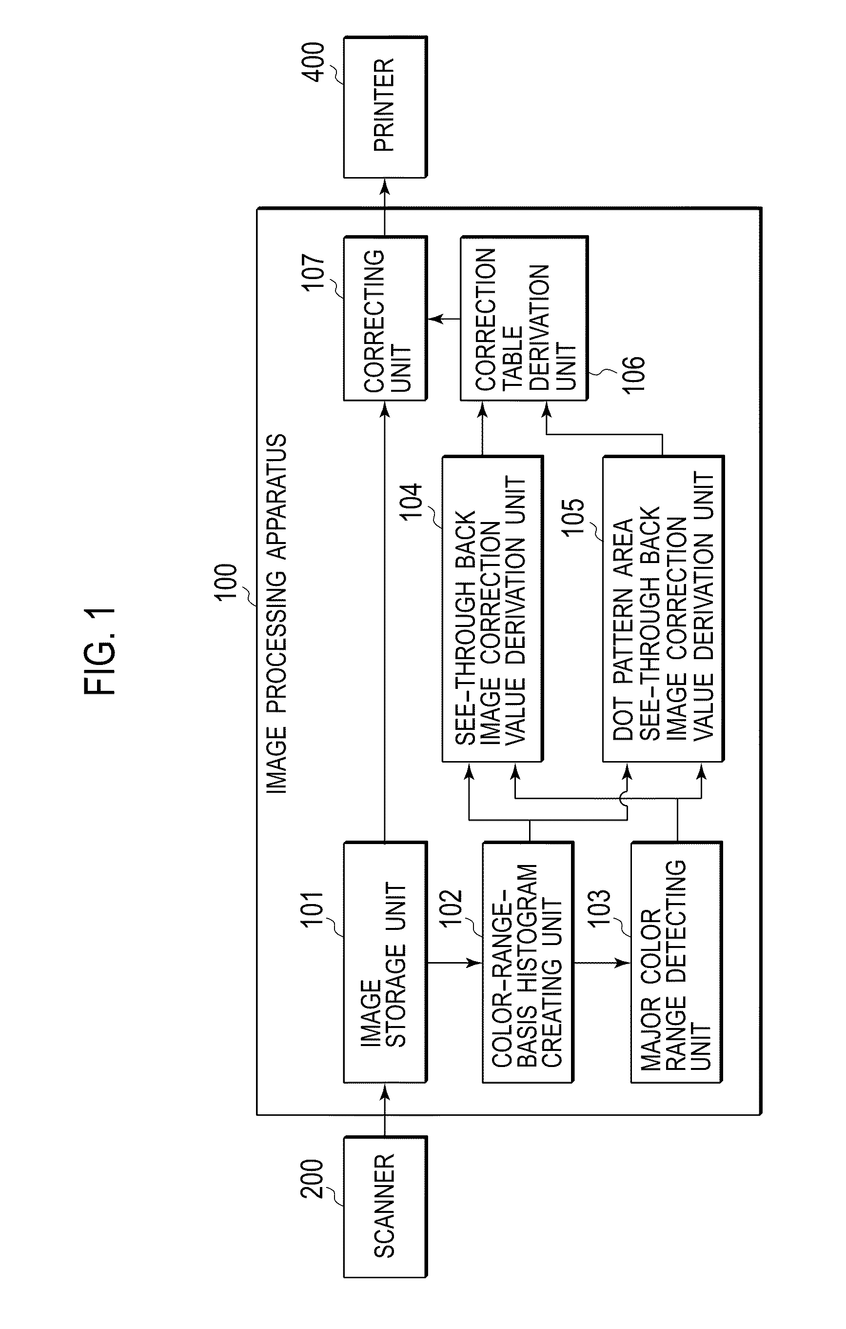
[0035]FIG. 1 is a functional block diagram of image processing apparatus 100 of the first embodiment.

[0036]Image processing apparatus 100 includes image storage unit 101, color-range-basis histogram creating unit 102, major color range detector 103, see-through back image correction value derivation unit 104, dot pattern area see-through back image correction value derivation unit 105, correction table derivation unit 106, correcting unit 107 and the like. These units function, when CPU 304 runs the control programs for image processing on RAM 302.

[0037]Image storage unit 101 is a functional unit for converting image data composed of RGB values that is acquired from scanner 200 via scanner I / F 301, from an RGB color space into a CIEL*a*b* color space. The converted image data is stored in RAM 302 and is output to color-range-basis histogram creating unit 102 and correcting unit 107. In the CIE L*a*b* color space, dimension L represents lightness and dimensions a, b represent chromat...

second embodiment

[0073]FIG. 9 is a functional block diagram of image processing apparatus 100 according to a second embodiment.

[0074]Image processing apparatus 100 comprises image storage unit 501, color-range-basis histogram creating unit 502, major color range detecting unit 503, see-through back image correction value derivation unit 504, dot pattern area see-through back image correction value derivation unit 505, correction table derivation unit 506, correction unit 507, background area determining unit 508 and the like. Similarly to the first embodiment, these units function when CPU 304 runs corresponding image processing control programs on RAM 302.

[0075]Note that image storage unit 501, correction table derivation unit 506 and correction unit 507 in the second embodiment are the same as or similar to image storage unit 101, correction table derivation unit 106 and correcting unit 107 of the first embodiment (FIG. 1), respectively, and thus description thereof will be omitted.

[0076]Color-ran...


PUM


Abstract

An image processing apparatus includes a major color range detector detecting the major color range from the image data; a criteria density setting unit determining a density value where the largest number of pixels exists in a density histogram of the major color range as a criteria density; a first correction value derivation unit deriving a first correction value to change density values in a predetermined range higher than the criteria density to be closer to the criteria density; a second correction value derivation unit deriving a second correction value to change density values in a predetermined range lower than the criteria density to be closer to the criteria density; a correction table derivation unit deriving a gradation correction table based on the first correction value and the second correction value; and a correcting unit correcting density of the scanned image data based on the gradation correction table.

Description

CROSS REFERENCE TO RELATED APPLICATIONS[0001]This application claims priority based on 35 USC 119 from prior Japanese Patent Application No. P2008-263703 filed on Oct. 10, 2008, entitled “Image Processing Apparatus”, the entire contents of which are incorporated herein by reference.BACKGROUND OF THE INVENTION[0002]1. Field of the Invention[0003]The invention relates to an image processing apparatus operable to process scanned image data.[0004]2. Description of Related Art[0005]When a printer photocopies a front side image of an original, “traces of an image on the back side of the original” are sometimes also reproduced in the copy, which is a phenomenon where a back side image of the original is slightly printed on a print medium.[0006]An art for preventing such a duplication of the see-through back side image is disclosed in Japanese Patent Application Laid-Open No. 2005-80152 (hereinafter, referred to as Document 1), for example.[0007]Document 1 scans one side of an original havi...

Claims


Application Information

Patent Timeline
IPC IPC(8): G03F3/08
CPCG06T5/009H04N1/4095G06T2207/10008G06T5/40
Inventor IWAMOTO, TAKARA
Owner OKI DATA CORP
Why Eureka
Try Eureka