Methods and apparatuses for positioning and securing safing insulation

a technology of safing insulation and positioning apparatus, which is applied in the field of insulation, can solve the problems of reducing the ability of safing insulation to prevent, bending, bowing, etc., and achieving the effect of preventing smoke, hot gasses, and/or fir

Active Publication Date: 2010-05-06
THERMAFIBER
View PDF29 Cites 45 Cited by
  • Summary
  • Abstract
  • Description
  • Claims
  • Application Information

AI Technical Summary

Benefits of technology

[0008]The present invention provides methods and apparatuses for securing safing insulation in the gap formed between a spandrel and a slab. Additionally, the present invention eliminates the need for stiffening tees and / or stiffening brackets. In one exemplary embodiment, the present invention utilizes an additional portion of spandrel insulation that is secured to the main spandrel insulation positioned against the spandrels of an exterior wall structure. This additional portion of spandrel insulation is positioned adjacent to a portion of compressed safing insulation positioned between the spandrel insulation and the slab. By fixedly securing this additional portion of spandrel insulation adjacent to the compressed safing insulation, any deformation of the main spandrel insulation that is caused by the forces exerted by the compressed safing insulation on the main spandrel insulation results in the additional portion of spandrel insulation moving in conjunction with the deformed main spandrel insulation. As a result, the deformation of the main spandrel insulation does not result in the creation of a gap between the compressed safing insulation and the spandrel insulation. Thus, the safing insulation continues to achieve its desired level of effectiveness by preventing smoke, hot gasses, and / or fire from passing through the safing insulation.

Problems solved by technology

However, due to the compression of the safing insulation, the safing insulation exerts pressure on the spandrel insulation that may cause the spandrel insulation to bend, bow, or otherwise deform.
As a result of the deformation of the spandrel insulation, the safing insulation may decompress, which decreases the ability of the safing insulation to prevent the passage of smoke, hot gasses, and / or fire therethrough.
While stiffening tees and / or stiffening brackets are effective, stiffening tees and / or stiffening brackets are difficult to position and secure.
Specifically, due to the small space existing in the gap formed between the perimeter edge of the slab and the spandrel insulation, the amount of time and effort needed to properly install the stiffening tees and / or stiffening brackets is increased.

Method used


Image

  • Methods and apparatuses for positioning and securing safing insulation
  • Methods and apparatuses for positioning and securing safing insulation
  • Methods and apparatuses for positioning and securing safing insulation

Examples


Embodiment Construction

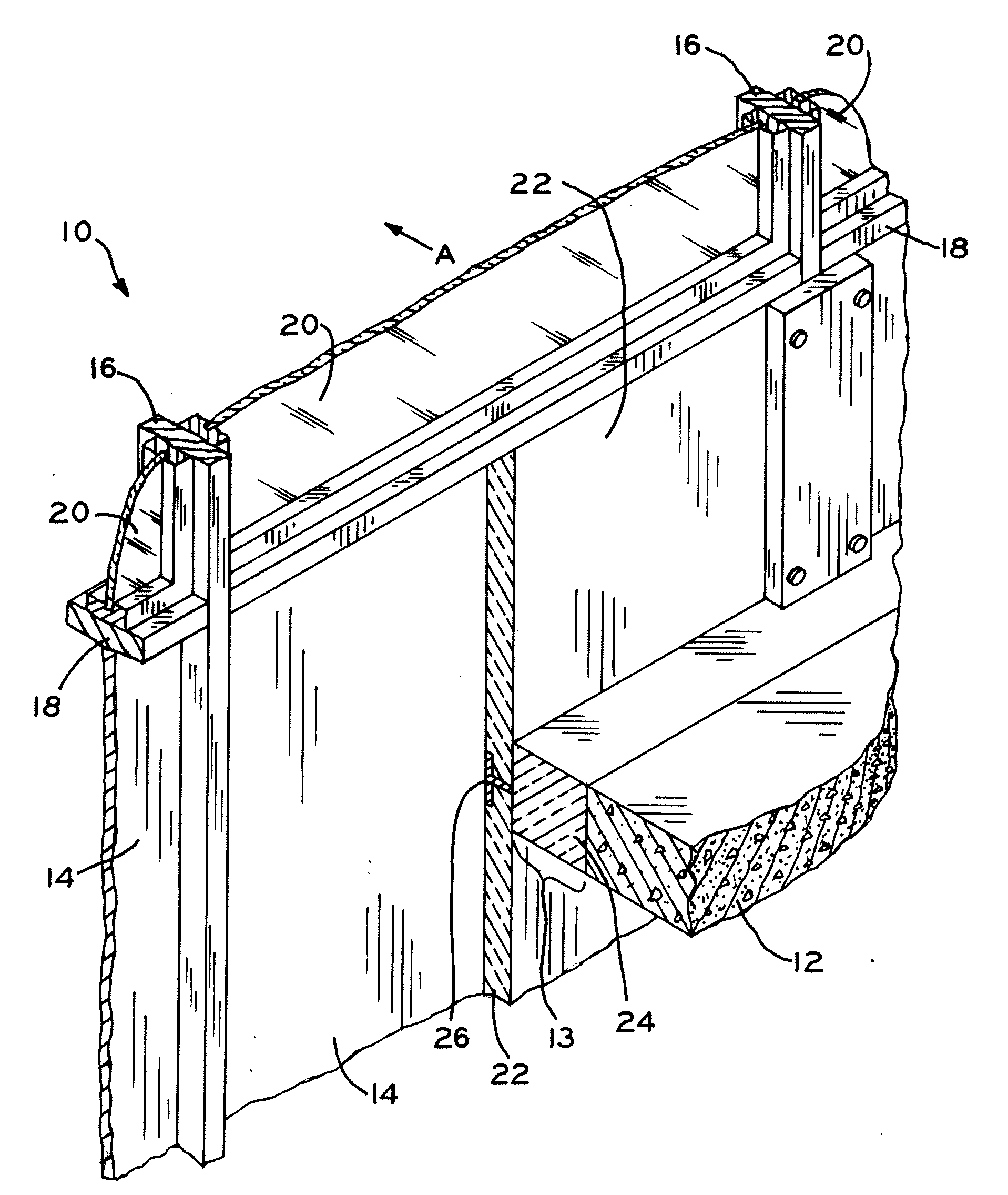
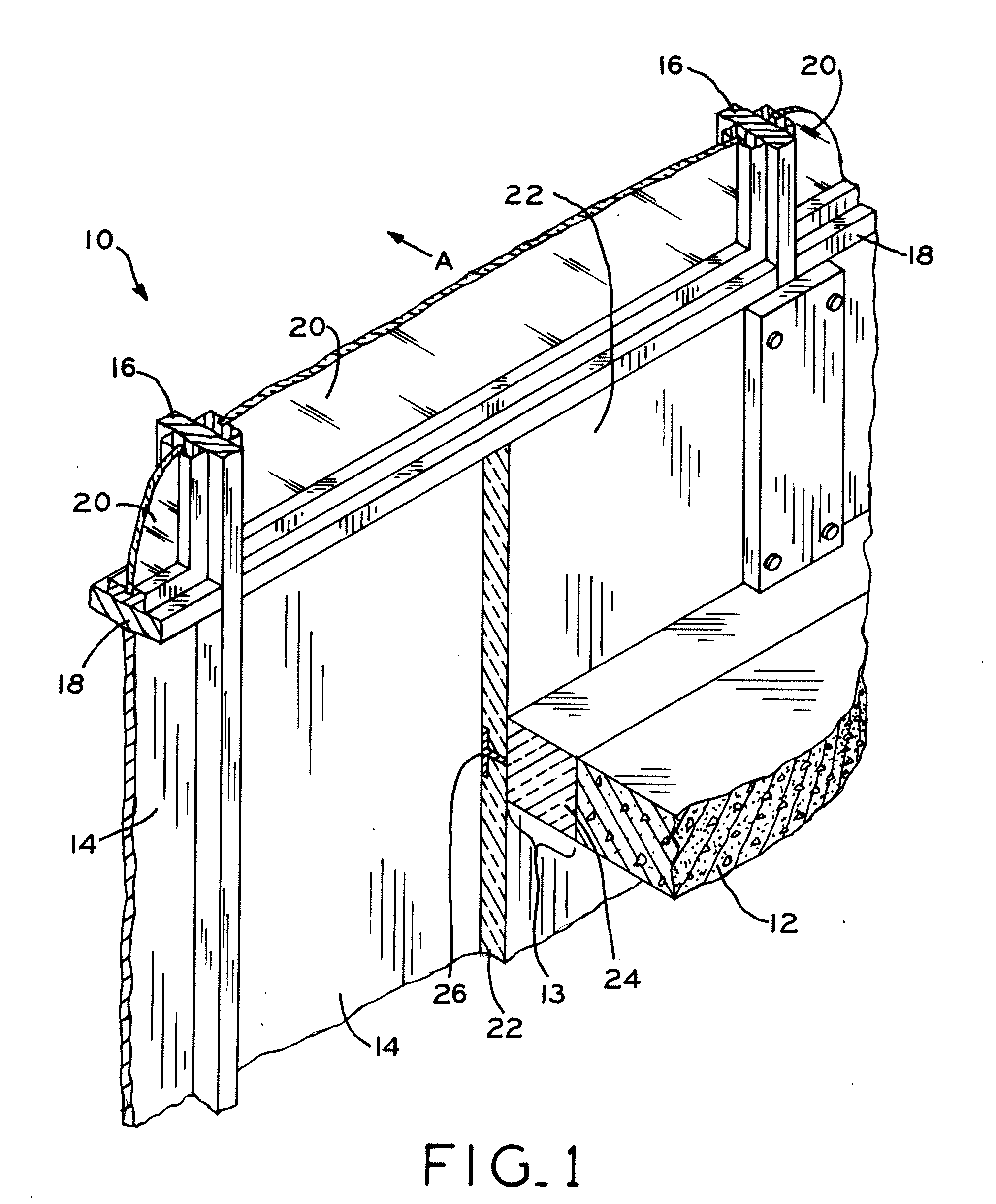
[0024]Referring to FIG. 1, an exterior wall system is depicted generally at numeral 10. Wall system 10 is connected to slab 12, which forms one of the floors of a multi-floor building. Wall system 10 includes spandrels 14 that, in one exemplary embodiment, define the exterior facade of the building. In one exemplary embodiment, spandrels 14 cover the area between the sill of a first vision glass installation and the head of a second vision glass installation. Spandrel 14 is secured to mullions 16, which provide the vertical framework for wall system 10. Extending between mullions 16 are transoms 18, which provide the horizontal framework for wall system 10. Additionally, vision glass 20 may be positioned between portions of mullions 16 and transoms 18. In this manner, spandrels 14 and vision glass 20, provide the visible, aesthetic features of exterior wall system 10.

[0025]Referring to FIG. 1, main spandrel insulation 22 is positioned between spandrels 14 and slab 12 and, in one exe...


PUM


Abstract

The present invention provides methods and apparatuses for securing safing insulation in the gap formed between a spandrel and a slab. Additionally, the present invention eliminates the need for stiffening tees and/or stiffening brackets. In one exemplary embodiment, the present invention utilizes a first portion of safing secured to spandrel insulation positioned in an exterior wall structure and a second portion of safing insulation positioned adjacent to the first portion of safing insulation and between the spandrel insulation and the slab. By fixedly securing the first portion of safing insulation to the spandrel insulation, any deformation of the spandrel insulation caused by the forces exerted by the compressed second portion of safing insulation on spandrel insulation results in the first portion of safing insulation moving with the spandrel insulation.

Description

BACKGROUND[0001]1. Field of the Invention[0002]The present invention relates to insulation and, particularly, to methods and apparatuses for securing safing insulation.[0003]2. Description of the Related Art[0004]Modern, multiple story buildings may be formed with an external wall structure that is secured to a floor slab. The external wall structure, or curtainwall, is secured to the slab, which is made of concrete, at a distance spaced away from the slab. By creating a gap between the slab and the curtainwall, proper alignment of the curtainwall is ensured. For example, in the event that the slab for a particular floor is not entirely straight or the slabs of adjacent floors are not properly aligned, the size of the gap between the curtainwall and a slab may be adjusted at various points along the slab to align the curtainwall so that it is substantially straight along the entire length and / or height of the building.[0005]While the gap created between the curtainwall and the slabs...

Claims


Application Information

Patent Timeline
Patent Type & Authority Applications(United States)
IPC IPC(8): E04B1/94E04B2/30
CPCE04B2/96E04B2001/7679E04B1/946E04B1/947E04B2/967E04B2/965
Inventor SHRIVER, JAMES
Owner THERMAFIBER
Why Eureka
Try Eureka