Eureka AIR delivers breakthrough ideas for toughest innovation challenges, trusted by R&D personnel around the world.

Phased-locked loop (PLL) synthesizer-synthesizer with improved voltage-controlled oscillator (VCO) pre-tuning

a phase-locked loop and voltage-controlled oscillator technology, applied in the direction of pulse automatic control, electric apparatus, etc., can solve the problems of noise suppression levels, contrary to the optimisation of loop dynamics and noise suppression, and achieve the effect of preventing any additional noise input and minimizing the cost of the circui

Active Publication Date: 2009-02-12
ROHDE & SCHWARZ GMBH & CO KG
View PDF5 Cites 9 Cited by
  • Summary
  • Abstract
  • Description
  • Claims
  • Application Information

AI Technical Summary

Benefits of technology

[0005]Accordingly, there exists a need for providing a PLL synthesizer, wherein any possible additional noise input is prevented, and at the same time, the cost of the circuit is minimized.
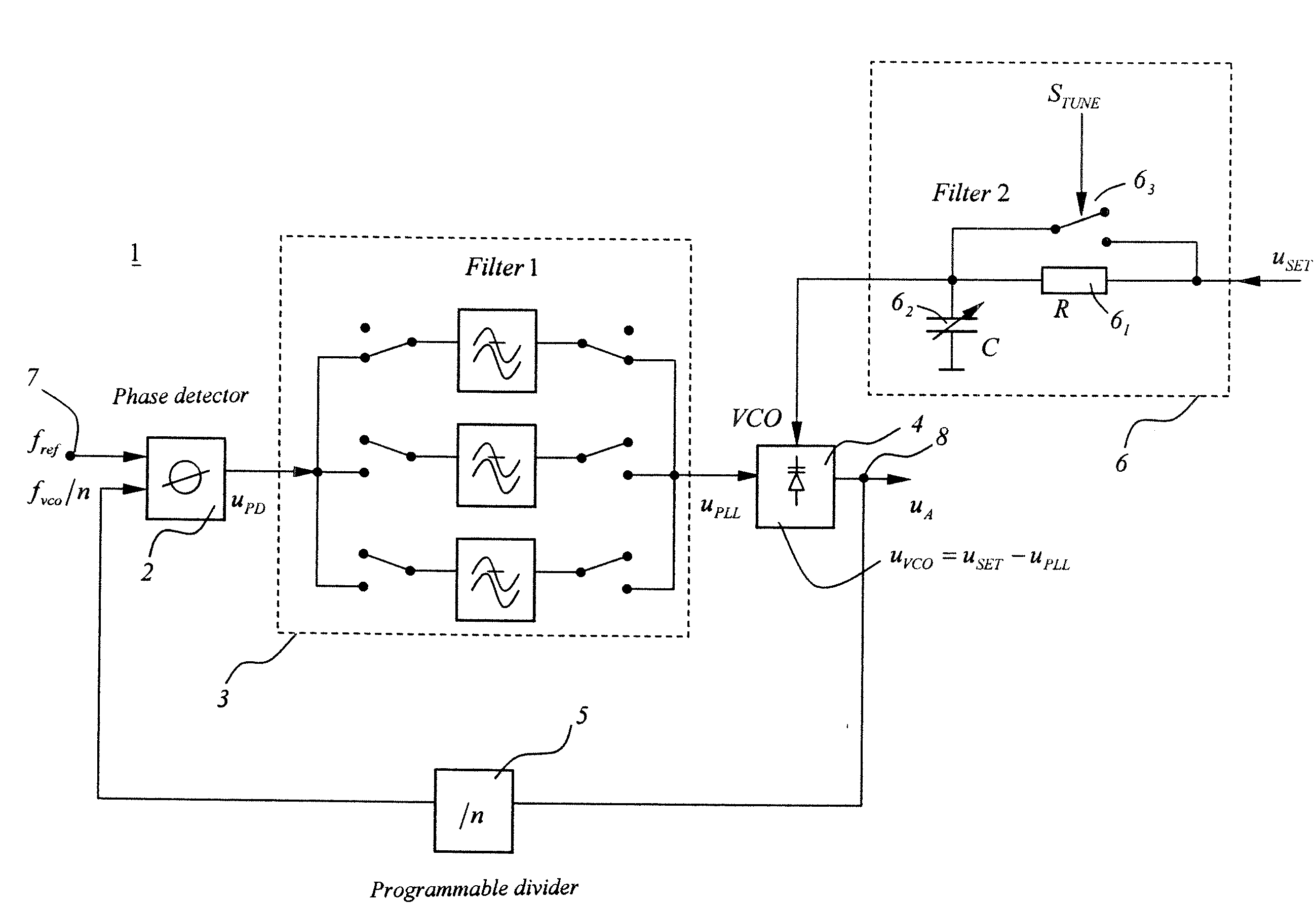
[0007]In accordance with one embodiment of the present invention, further filter levels are avoided, and only passive circuit elements are used. Further filter levels for noise suppression have the additional disadvantage of having a direct influence on the loop dynamics, and, in the design of PLL synthesizers, they are also contrary to the optimisation of the loop dynamics and noise suppression. In an exemplary embodiment, a frequency-selection voltage is introduced as passively as possible and ideally directly in the VCO. This allows the above-named filter levels to be avoided, and a common treatment of the main noise-influencing factors and control dynamics is possible with only one filter.
[0010]In accordance with one embodiment of the present invention, a noise-laden voltage for rough frequency selection uSET can be filtered in an extreme manner without influencing the loop dynamics as a result. The required voltage uSET is normally stored in a frequency-dependent manner in an electronic memory and is made available by a digital-analog converter. The switch is normally controlled in a digital manner, wherein the switching times are adapted to the desired loop bandwidth. The voltage uSET specified in this manner is noise-laden and must be filtered. An R-C low-pass filter circuit pre-chargeable via a switch is used as the preferred circuit. As a result of a pre-charging of the capacitor of the low-pass filter circuit, the time constant can be bridged, and the filter can be used immediately for filtering the voltage uSET. On the one hand, the voltage is therefore immediately supplied in the full amplitude thereby providing an optimum switching voltage.
[0011]On the other hand, higher-frequency noise components, which cannot be suppressed from the phase-control circuit, are blocked by a narrow-band filter. In this manner, rapid frequency-change rates can be achieved; the design of the loop dynamic can be made completely independent of the design of the filtering; and, at the same time, an extremely narrow-band filtering of the voltage uSET can be achieved.
[0012]Moreover, other methods for coupling a bias voltage are possible. A charging capacitor connected in parallel in a switchable manner to the capacitor of the R-C low-pass filter, which additionally smoothes the output voltage, can also be used. In this case also, other realizations can be used, for example, a second capacitor can be provided in parallel, in a switchable manner, with a time offset, so that the charging current does not exceed a maximum amplitude.

Problems solved by technology

Further filter levels for noise suppression have the additional disadvantage of having a direct influence on the loop dynamics, and, in the design of PLL synthesizers, they are also contrary to the optimisation of the loop dynamics and noise suppression.

Method used


Image

  • Phased-locked loop (PLL) synthesizer-synthesizer with improved voltage-controlled oscillator (VCO) pre-tuning
  • Phased-locked loop (PLL) synthesizer-synthesizer with improved voltage-controlled oscillator (VCO) pre-tuning
  • Phased-locked loop (PLL) synthesizer-synthesizer with improved voltage-controlled oscillator (VCO) pre-tuning

Examples


Embodiment Construction

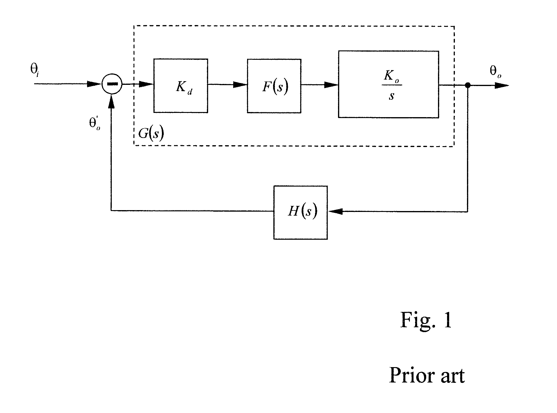
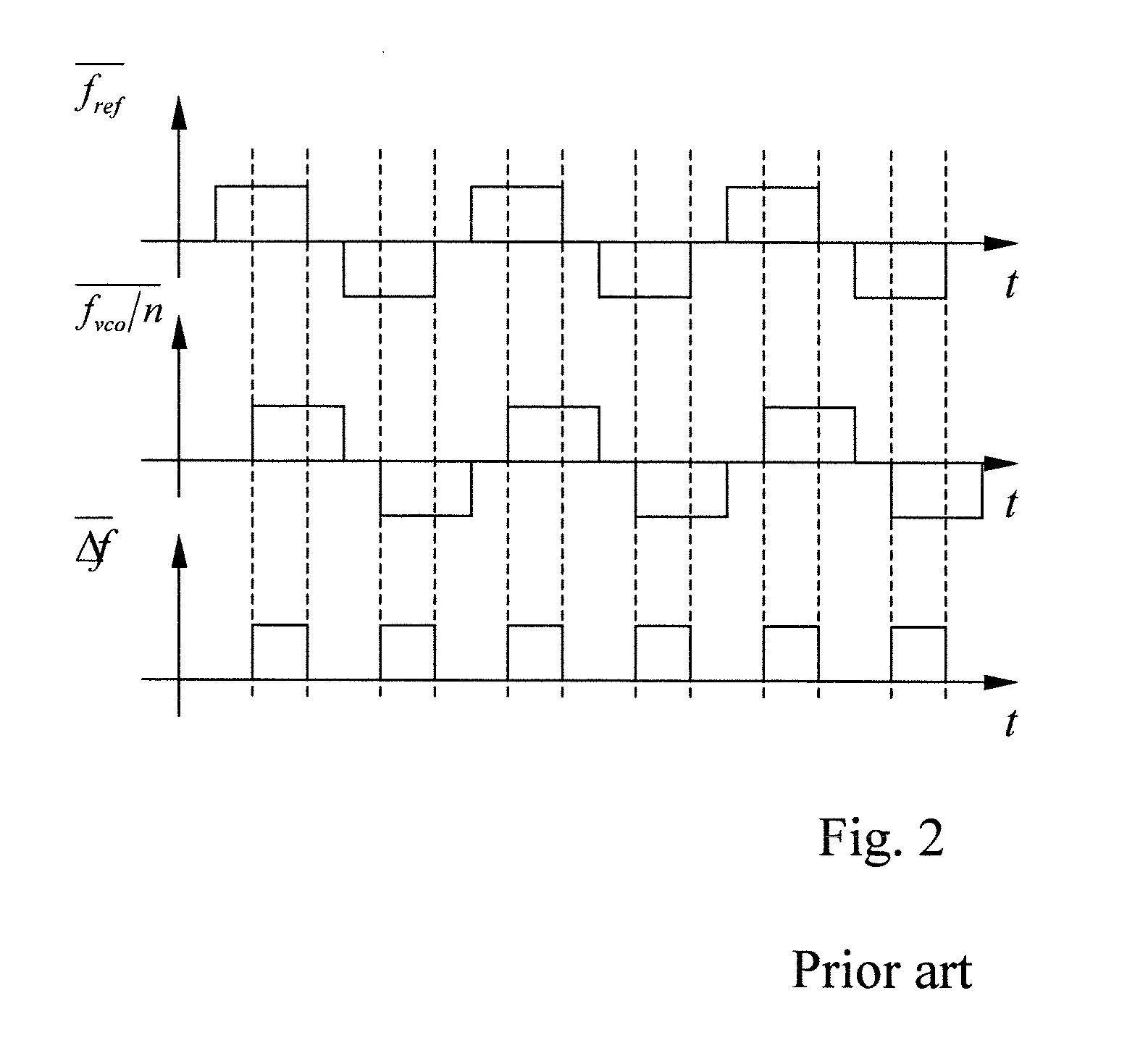
[0020]Before describing the various embodiments of the present invention in greater detail, some basic principles of PLL synthesizers or respectively control circuits will first be explained below with reference to FIGS. 1 and 2 as a basis for understanding the invention. An exemplary embodiment of the circuit according to the invention is then described with reference to FIGS. 3, 4 and 5.

[0021]The principle of the phase-locked loop (referred to below as PLL) is based on a comparison of a reference signal with an actual signal or output signal. In this context, the reference signal is generated with a high-precision quartz oscillator. Using a programmable divider, it is possible to generate signals with a frequency, which can be specified within a wide framework. So-called phase detectors (referred to below as PD) or phase comparators are used for the comparison of the signals.

[0022]The method of operation of a PD will first be modelled in a linear manner. This condition is fulfille...


PUM


Abstract

An apparatus for providing Phased-Locked Loop (PLL) synthesis comprises a phase detector, at least one switchable filter, an oscillator controlled by a control voltage (uPLL) and a divider. The controlled oscillator has two inputs, wherein the control voltage (uPLL) is coupled to a first input, and a selection voltage (uSET) for rough frequency adjustment is coupled to a second input. Both voltages establish the frequency of the oscillator.

Description

FIELD OF THE INVENTION[0001]The present invention, according to various embodiments, relates to a PLL (phase-locked loop) synthesizer.BACKGROUND OF THE INVENTION[0002]PLL (phase-locked loop) synthesizers are used in many contexts. For example, they are used in mobile-telephone technology, measurement technology and high-frequency measurement technology. PLL synthesizers are based on a reference oscillator or quartz oscillator, of which the frequency provides the basis for a specified output signal. A phase detector compares the reference frequency specified by the oscillator with the desired signal frequency and issues corresponding voltage pulses. These are then further processed in an integrator or filter circuit and supplied to a voltage-controlled oscillator (VCO). This adapts the frequency of the output oscillation according to the input specification, which, in the phase comparator or detector, is then supplied to the phase detector again via a feedback loop.[0003]On the basis...

Claims


Application Information

Patent Timeline
IPC IPC(8): H03L7/00
CPCH03L7/099H03L2207/06H03L7/189H03L7/107H03L7/104
Inventor SCHECHINGER, ALOIS
Owner ROHDE & SCHWARZ GMBH & CO KG
Why Eureka
Eureka Blog
Learn More