Inverter device and electric device using same

a technology of inverter device and electric device, which is applied in the direction of motor/generator/converter stopper, polyphase induction motor starter, dynamo-electric converter control, etc., can solve the problems of large driving power, difficult to maximize the efficiency of inverter device, and large circuit loss, so as to reduce circuit cost, low circuit loss, and high efficiency

Inactive Publication Date: 2012-08-23
CAMBRIDGE MOBILE TELEMATICS INC +1
View PDF2 Cites 12 Cited by
  • Summary
  • Abstract
  • Description
  • Claims
  • Application Information

AI Technical Summary

Benefits of technology

[0011]Thereby, it is possible to reduce circuit costs, and to implement an inverter device having a low circuit loss and high efficiency by optimally controlling driving of the switching elements.
[0012]An electric apparatus of the present invention has a configuration where the inverter device is used for a driving device of a motor. Thereby, it is possible to implement an electric apparatus having good driving efficiency at low cost.

Problems solved by technology

However, since, in the inverter device, the upper arm switching circuit and the lower arm switching circuit are constituted by different kinds (the IGBT and the MOSFET) of voltage-driven switching elements, it is difficult to maximize efficiency of the inverter device in consideration of both of conduction loss and switching loss of the different switching elements.
However, in the inverter circuit, in the voltage-driven switching elements of the upper arm switching circuit and the lower arm switching circuit, it is difficult to reduce circuit loss such as the conduction loss or switching loss or to perform high-speed driving.
Therefore, if a current-driven switching element which has small circuit loss and can perform high-speed driving is used for the upper arm switching circuit and the lower arm switching circuit, large driving power is necessary.
As a result, it is not possible to implement a high efficiency, small-sized, light-weighted, and low cost inverter circuit.

Method used


Image

  • Inverter device and electric device using same
  • Inverter device and electric device using same
  • Inverter device and electric device using same

Examples


first exemplary embodiment

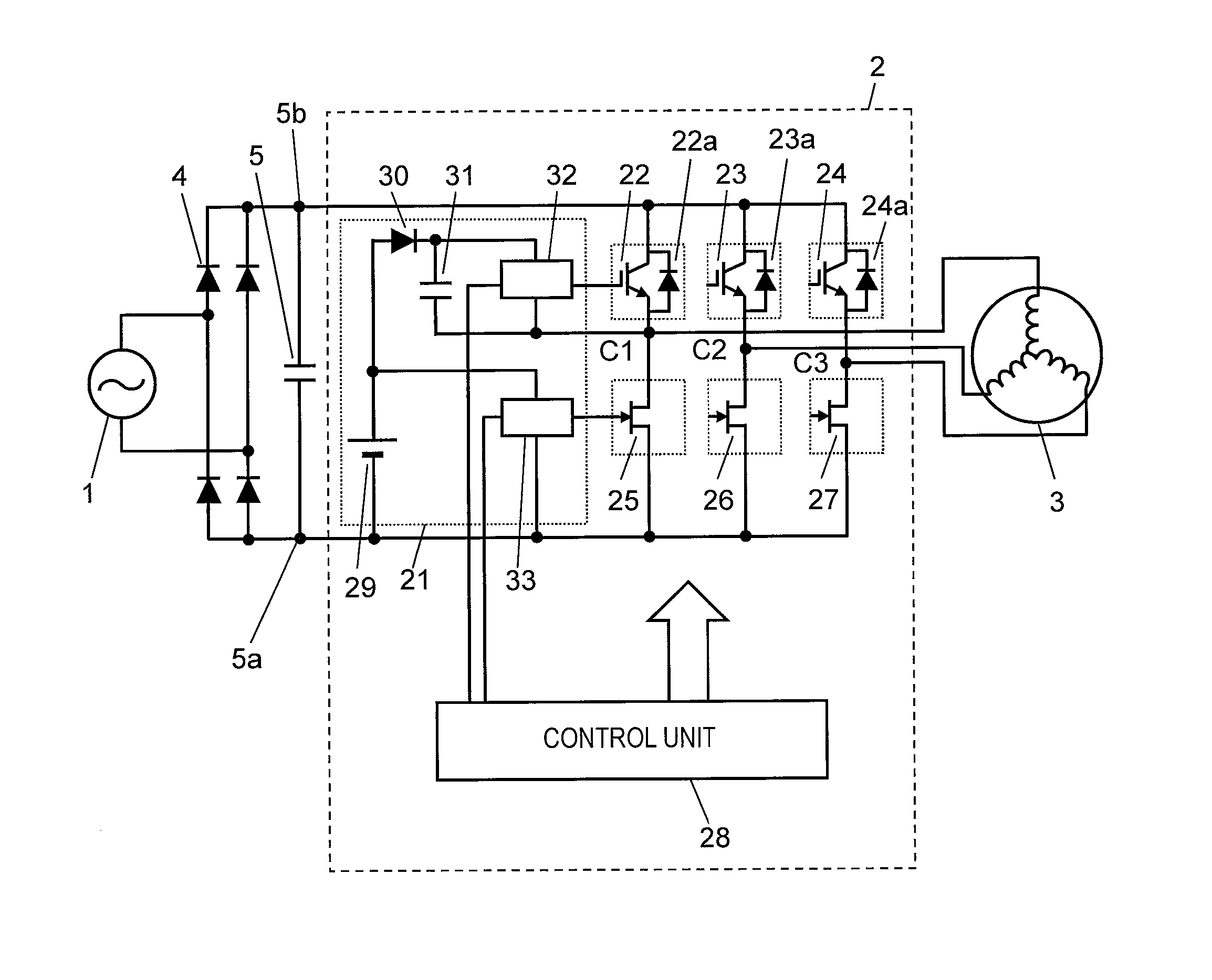
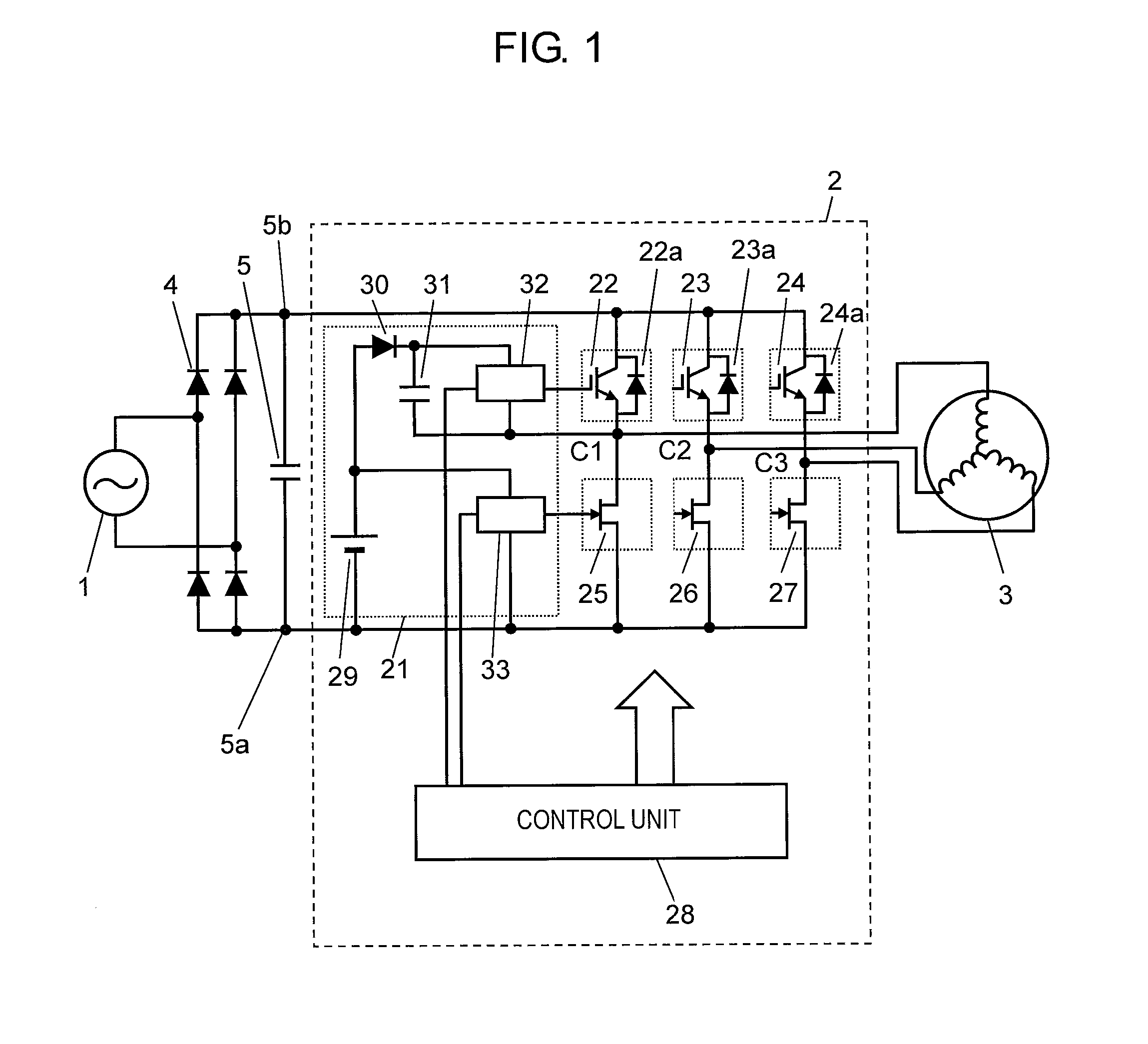
[0023]FIG. 1 is a configuration diagram illustrating a configuration of an inverter device according to a first embodiment.

[0024]As shown in FIG. 1, AC power input from AC power supply 1 is temporarily converted into a DC power supply voltage by rectifying circuit 4 and smoothing capacitor 5 so as to be applied to inverter device 2, and three-phase (a U phase, a V phase, and a W phase) signals output from inverter device 2 are applied to by control unit 28 and drive motor 3.

[0025]Here, inverter device 2 is constituted by an upper arm switching circuit including switching elements 22, 23 and 24, a lower arm switching circuit including switching elements 25, 26 and 27, driving circuit 21 including bootstrap circuits, and control unit 28 controlling them. Respective corresponding pairs (22 and 25), (23 and 26) and (24 and 27) of the switching elements of the upper arm switching circuit and the lower arm switching circuit are connected in series and form three-phase serial circuits. In ...

second exemplary embodiment

[0058]Hereinafter, an inverter device according to a second embodiment of the present invention will be described in detail with reference to the drawings. A configuration of the inverter device according to the second embodiment is the same as that of the inverter device according to the first embodiment. In the same manner, control unit 28 controls inverter device 2 so as to output AC power where motor 3 rotates at a desired rotation rate. At this time, switching elements 22 to 27 are controlled through the pulse width modulation (PWM) where a time width of the driving pulse of the sinusoidal voltage is adjusted and is output.

[0059]FIG. 6 is a diagram illustrating a driving method of the inverter device according to the second embodiment of the present invention.

[0060]As shown in FIG. 6, the driving method is a method in which, in relation to minimal voltages of three-phase (a U phase, a V phase, and a W phase) output voltages output from the inverter device, only a single phase i...

third exemplary embodiment

[0088]Hereinafter, an electric apparatus according to a third embodiment of the present invention will be described with reference to the drawing by exemplifying a vacuum cleaner.

[0089]FIG. 9 is a cutaway perspective view illustrating an outline of the vacuum cleaner according to the third embodiment of the present invention.

[0090]That is to say, the embodiment has the inverter device described in the first embodiment or the second embodiment embedded therein, and is used as a driving device of a motor for the fan of the vacuum cleaner.

[0091]Specifically, as shown in FIG. 9, the vacuum cleaner outputs AC power, which is input via power receptacle 92, at a predetermined output frequency via the inverter device, and drives, for example, motor 91 for a fan such as an inverter fan motor, inside vacuum cleaner main body 90. Thereby, the fan rotates at a predetermined rotation rate, and the vacuum cleaner suctions dust and the like.

[0092]That is to say, according to the present embodiment...


PUM


Abstract

The present invention relates to an inverter device including an upper arm switching circuit, a lower arm switching circuit, a control unit that controls the upper arm switching circuit and the lower arm switching circuit, a plurality of voltage-driven switching elements forming the upper arm switching circuit, a plurality of current-driven switching elements forming the lower arm switching circuit, and a bootstrap circuit that applies a driving voltage to the switching elements of the upper arm switching circuit and the lower arm switching circuit. With this configuration, the circuit loss is reduced and thus efficiency is improved.

Description

TECHNICAL FIELD[0001]The present invention relates to an inverter device which includes a plurality of switching elements and drives a load such as a motor, and an electric apparatus using the same, and particularly to a vacuum cleaner using the inverter device for a driving device of a fan motor.BACKGROUND ART[0002]An inverter device converts input power from a power supply into AC of a desired output frequency, which is used to drive a motor or the like. The inverter device generally includes a switching circuit which has a plurality of serial circuits where two switching elements on the upstream side and the downstream side according to an application direction of the power supply voltage are connected in series to each other. Hereinafter, the switching circuit forming the upstream side is referred to as an “upper arm switching circuit”, and the switching circuit forming the downstream side is referred to as a “lower arm switching circuit”. As the switching element, a voltage-dri...

Claims


Application Information

Patent Timeline
Patent Type & Authority Applications(United States)
IPC IPC(8): H02P27/06H02M7/537
CPCH02M1/084H02M7/5388Y02B70/1491H02P27/085H02M2001/0054H02M1/0054Y02B70/10
Inventor MATSUI, KEIZOUIMAI, MAKOTO
Owner CAMBRIDGE MOBILE TELEMATICS INC
Why Eureka
Try Eureka