Digital signal reproducing apparatus

Inactive Publication Date: 2009-10-15
PANASONIC SEMICON SOLUTIONS CO LTD
View PDF6 Cites 12 Cited by
  • Summary
  • Abstract
  • Description
  • Claims
  • Application Information

AI Technical Summary

Benefits of technology

[0010]Since the present invention allows the use of a reproduced clock having a low frequency, the circuit scale and power consumption of an apparatus for performing high-speed recor

Problems solved by technology

As a recording/reproduction speed increases, cost and pow

Method used


Image

  • Digital signal reproducing apparatus
  • Digital signal reproducing apparatus
  • Digital signal reproducing apparatus

Examples


Example

Embodiment 1

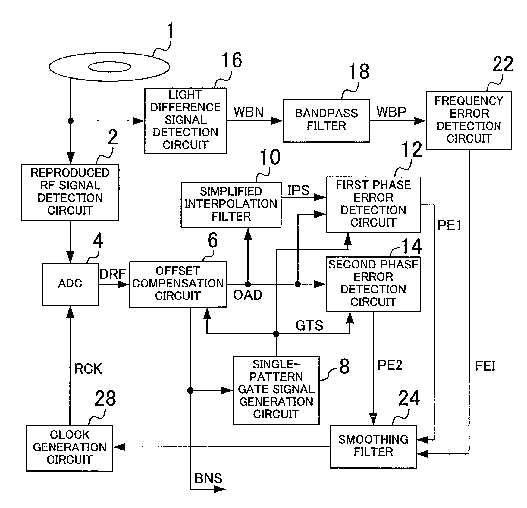
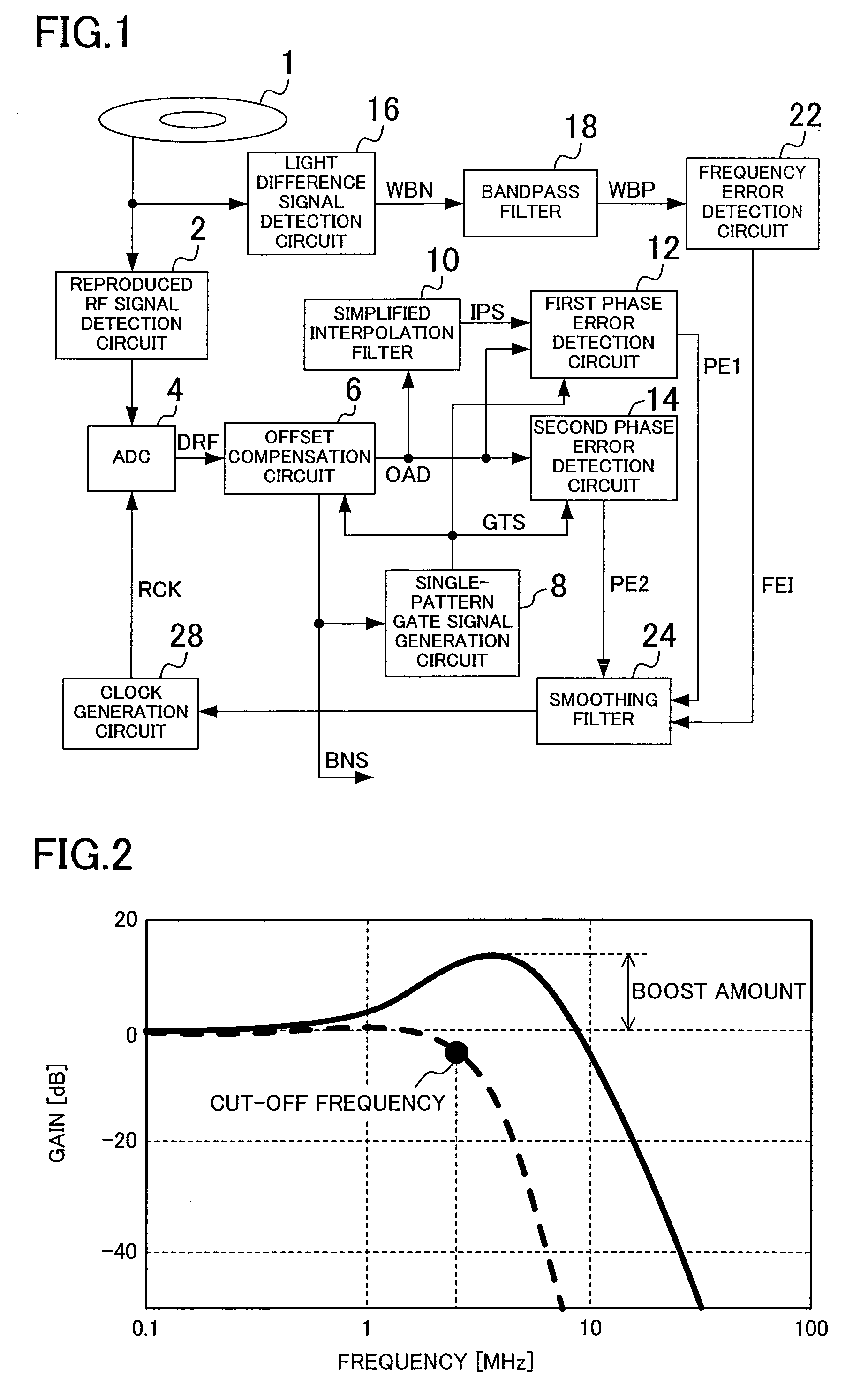
[0049]FIG. 1 is a block diagram showing a structure of a digital signal reproducing apparatus according to the first embodiment of the present invention. The digital signal reproducing apparatus of FIG. 1 includes a reproduced RF signal detection circuit 2, an analog to digital converter (hereinafter referred to as ADC) 4, an offset compensation circuit 6, a single-pattern gate signal generation circuit 8, a simplified interpolation filter 10, a first phase error detection circuit 12, a second phase error detection circuit 14, a light difference signal detection circuit 16, a bandpass filter 18, a frequency error detection circuit 22, a smoothing filter 24, and a clock generation circuit 28. The digital signal reproducing apparatus of FIG. 1 is used not only in the case of performing reproduction from a DVD-RAM disk 1 as an optical recording medium but also in the case of performing recording in the DVD-RAM disk 1.

[0050]To the reproduced RF signal detection circuit 2, a ...

Example

Embodiment 2

[0096]FIG. 11 is a block diagram showing a structure of a digital signal reproducing apparatus according to the second embodiment of the present invention. The digital signal reproducing apparatus of FIG. 11 further includes a power control unit 32, a partial response equalizer 36, a Nyquist interpolation filter 37, and a maximum likelihood decoder (Viterbi decoder) 38 in addition to the components of the digital signal reproducing apparatus of FIG. 1, while including a first phase error detection circuit 212 instead of the first phase error detection circuit 12. The power control unit 32 has a power gate signal generation circuit 33 and a power stop circuit 34.

[0097]FIG. 12(a) is a block diagram showing an example of a structure of the first phase error detection circuit 212 of FIG. 11. FIG. 12(b) is view illustrating the principle of the detection of the phase error information PE1 by the first phase error detection circuit 212 of FIG. 12(a).

[0098]As shown in FIG. 12(a...


PUM


Abstract

A digital signal reproducing apparatus includes an analog to digital converter for sampling and quantizing a signal read from an optical recording medium in accordance with a reproduced clock having a frequency which is one-half of a channel bit frequency and outputting an obtained digital RF signal, an offset compensation circuit for reducing an offset component in an amplitude direction from the digital RF signal, and a simplified interpolation filter for reconstructing a signal indicating a predetermined pattern recorded in the optical recording medium from the output signal of the offset compensation circuit and outputting the reconstructed signal. A control operation is performed to reduce the magnitudes of respective values shown by first phase error information on a section with the predetermined pattern and by second phase error information on a section other than the section with the predetermined pattern.

Description

TECHNICAL FIELD[0001]The present invention relates to an apparatus for performing signal processing to record digital data in an optical recording medium and reproduce digital data from an optical recording medium.BACKGROUND ART[0002]As a system for recording digital data in an optical recording medium (optical disk), a system which implements a uniform recording density over the recording medium by holding a linear velocity constant, such as a CD (Compact Disc (registered trademark)) or a DVD (Digital Versatile Disk), is mostly used. In recent years, attention has been focused not only on a read-only optical disk but also on a recordable DVD-RAM (DVD-Random Access Memory), a once-writable DVD-Recordable (hereinafter referred to as DVD-R), and a rewritable DVD-Rewritable (hereinafter referred to as DVD-RW). Because the DVD-RAM disk has a characteristic feature of enabling recording / reproduction by random access, it is appropriate as an information recording medium.[0003]The DVD-RAM ...

Claims


Application Information

Patent Timeline
IPC IPC(8): G11B27/30H03M1/12
CPCG11B20/10009G11B20/10046G11B20/10055G11B20/10083G11B20/10101G11B2220/2575G11B20/10222G11B20/1403G11B2020/1287G11B2220/2562G11B20/10111
Inventor OGURA, YOUICHIHIRAKI, TATSUSHITAKAO, YORIKAZU
Owner PANASONIC SEMICON SOLUTIONS CO LTD
Why Eureka
Try Eureka