
Versatile orthopaedic leg mounted walkers

Active Publication Date: 2007-12-04
OSSUR HF
View PDF19 Cites 111 Cited by
  • Summary
  • Abstract
  • Description
  • Claims
  • Application Information

AI Technical Summary

Benefits of technology

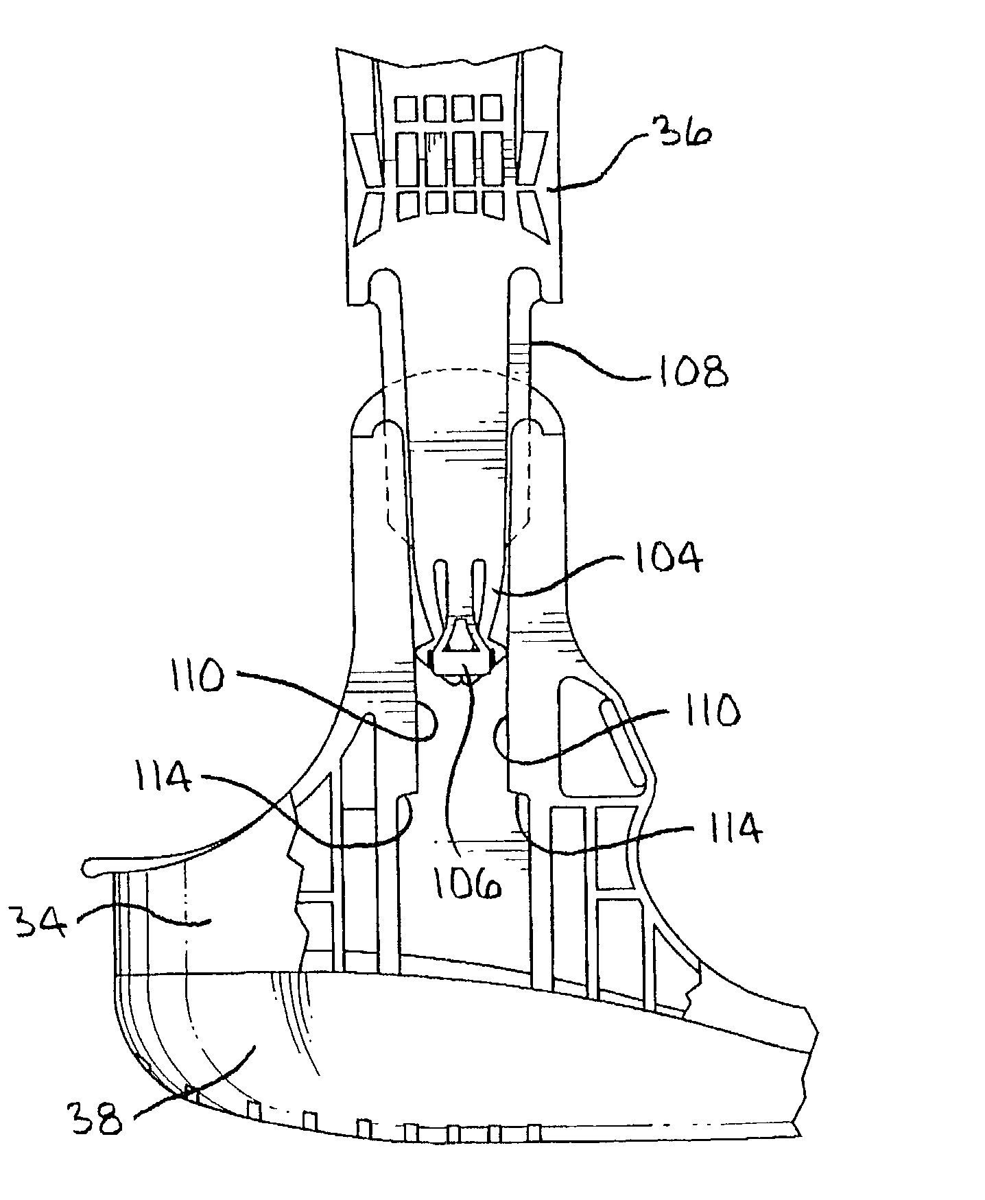
[0013]3. The struts may be provided with reduced thickness zones to increase flexibility and to accommodate different anatomical configurations without sacrificing stability. Reduced thickness zones located below the upper end of the struts but at least an inch or two above the ankle joint can provide medial / lateral flexibility or hinge points to accommodate patients with relatively large lower legs. It is also noted that the medial / lateral hinge action may be provided by physical hinges or pivot points along the length of the strut, rather than by reduced strut thickness.
[0014]4. The struts may be provided either at the juncture with the base or along their length, with variable resiliency mechanisms, to permit initial easy deflection to accommodate minor deflections of the struts, and with arrangements for increasing resistance to deflections greater than a predetermined distance or angle. These arrangements may include reduced thickness in the struts, and a stop which is engaged when the deflection exceeds a predetermined amount.
[0016]6. The outer sole or outsole of the walker may include protrusions which may be hollow or doughnut shaped, in its upper surface to provide resiliency and cushioning during walking. And the outsole may extend upward around the outer periphery of the base, and have a peripheral bead interfitting with a mating recess in the base and providing a continuous smooth exterior surface at the junction between the outsole and the base. The base may be cored from the sides at the central area of the walker, and may be cored with relative small recesses from the top, toward the front and rear of the base, to reduce the weight of the walker. The outsole extends over the side core openings, thereby preventing the entry of foreign material, and provides a pleasing aesthetic appearance.
[0020]Advantages of the new design include the elimination of decorative side caps, increased outsole adhesion to the plastic base, resistance to water, mud and dirt, increased surface contact and gripping action, increased resiliency between outsole and plastic base and improved aesthetic appearance resulting from the smooth outer surface mating of the outsole and the plastic base. The upward extent of the oustsole of the base, and the interfitting recess and groove also prevents delamination of the outsole from the base. Variations in the size of the ankles and lower leg are accommodated by living hinges and by increased flexibility within preset angular limits. Safety is assured by the triple locking mating arrangements between the struts and plastic base. Finally, costs are reduced by the use of integrally molded d-rings which may provide pivoting action, by the simplification of the walker structure, and by avoiding the need for different walker configurations for different anatomical configurations.

Problems solved by technology

However, the known prior art walkers suffer from various shortcomings or disadvantages.
In this regard, the exteriors of some walkers are irregular so that they may catch on adjacent objects or fabric, and do not have an aesthetically pleasing configuration.
Concerning the struts which normally extend upwardly from the base of the walker, (1) they may not include readily interchangeable long and short struts; (2); they may not readily accommodate different size lower legs; (3) the mechanisms for securing the struts to the base may be either permanent, or subject to failure; (4) the flexibility of the struts may be substantially linear, and therefore may be too flexible throughout bending cycles to provide adequate orthopaedic support, or may be unduly stiff so as to irritate the user.
Regarding the walker bases, some available walkers do not have adequate resiliency to prevent undue shock during walking motion such as heel strike or other shock.

Method used


Image

  • Versatile orthopaedic leg mounted walkers
  • Versatile orthopaedic leg mounted walkers
  • Versatile orthopaedic leg mounted walkers

Examples


Embodiment Construction

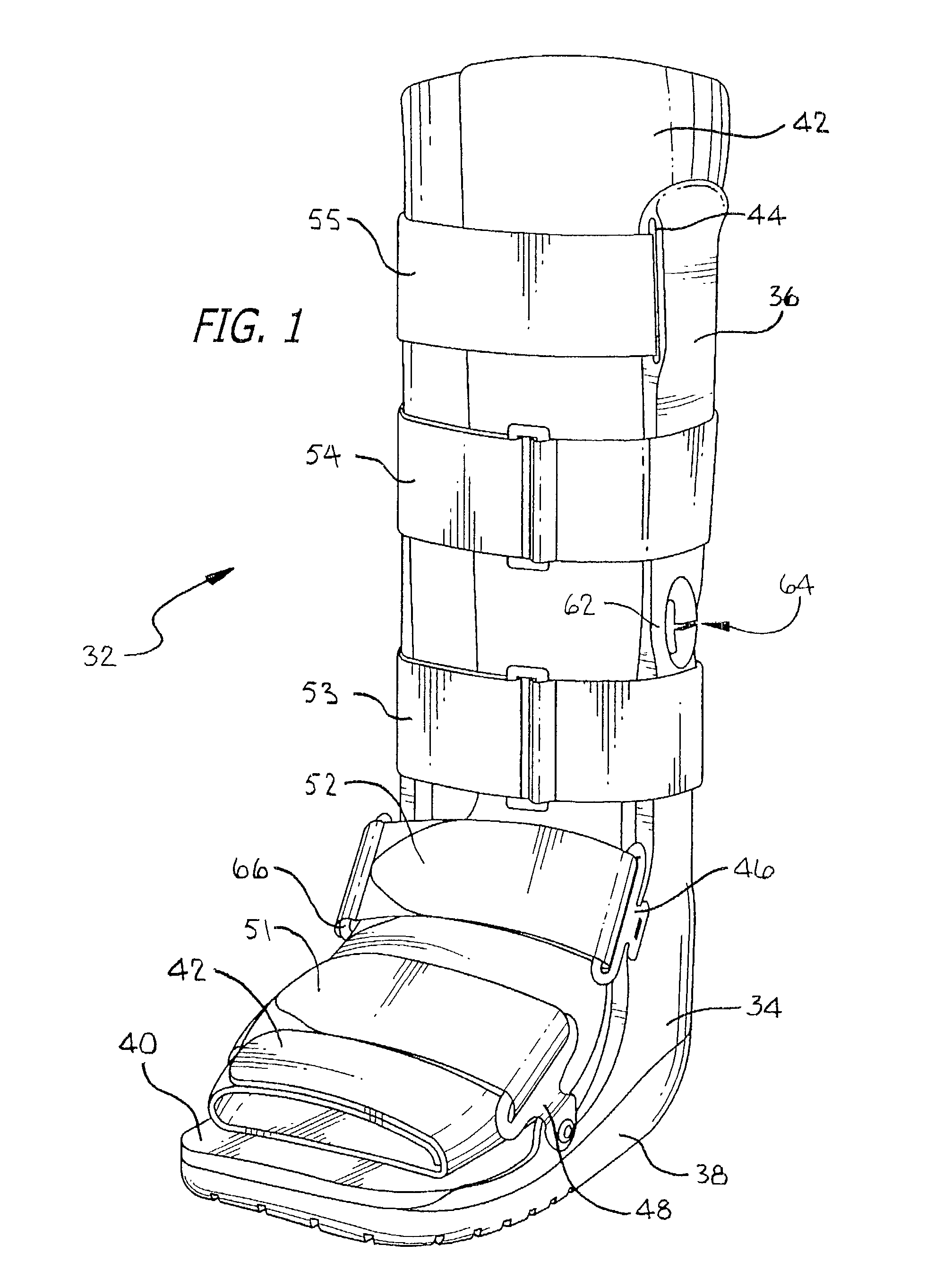
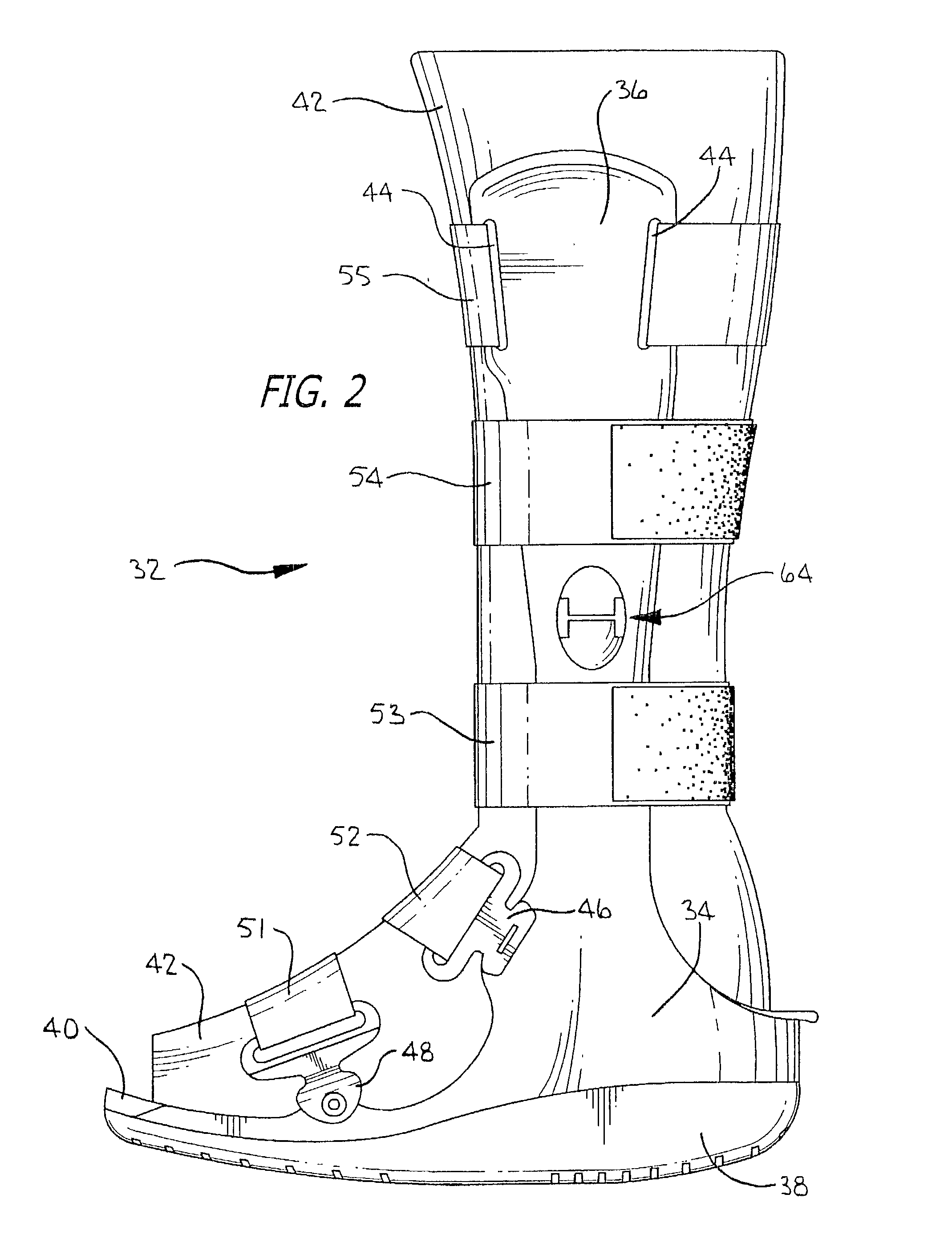
[0041]Referring more particularly to the drawings, FIG. 1 is a perspective view of a walker 32 illustrating the principles of the invention. The walker of FIG. 1 includes an engineered plastic base member 34, two struts, one of which is visible at reference 36, and an outersole, or outsole 38. The plastic base 34 may, for example be formed of fiber glass filled nylon, but other high strength plastics or other materials may be employed such as aluminum which may for example be powder coated. A resilient layer 40, which may be formed of one-quarter inch thick resilient foam, provides a cushion between the foot and the upper surface of the plastic base 34. Additional padding 42 extends around the foot, ankle and lower leg of the patient. The padding 42 is held in place between the struts including strut 36 by hook and loop material of the Velcro® type, with hook type material extending along the inner surface of the struts, and with the padding 42 either having mating loop material on ...


PUM


Abstract

A versatile orthopedic walker includes a high strength engineered plastic base with spaced upper and lower surfaces and upwardly extending slotted strut supports. The base may be laterally and vertically cored, and an outer sole is provided which extends upward over the core openings, with the upper edges of the outsole being ridged to fit into a peripheral groove in the base to provide a smooth exterior surface. Struts of different lengths are provided, and all of the struts have identical arrangements for interlocking with the base. All of the struts may be provided with a three pronged construction to triply lock the struts into the base. The struts may have areas of reduced cross-section providing pivot points or areas of flexibility to accommodate different size patients, and limiting stops may be provided to assure adequate orthopedic support. Fully integrally molded pivoting D-rings may hold walker straps in place.

Description

FIELD OF THE INVENTION[0001]This invention relates to orthopedic walkers, which are orthopedic support boots which encompass the foot, ankle and lower legs, for use by persons recovering from injuries such as broken bones or other trauma of the lower leg, ankle or foot. This type of orthopaedic product is often referred to as a “short leg walker”.BACKGROUND OF THE INVENTION[0002]Leg mounted orthopaedic walkers are well known, and typical patents disclosing such walkers include the following[0003]U.S. Pat. No. 5,368,5581Granted: Nov. 29, 1994Inventor: ZuckermanTitle: Ankle Brace WalkerU.S. Pat. No. 4,771,768Granted: Sep. 20, 1988Inventor: CrispinTitle: Controlled Motion Ankle FractureWalkerU.S. Pat. No. 5,078,128Granted: Jan. 7, 1992Inventor: Grim et al.Title: Removable Leg WalkerU.S. Pat. No. 5,329,705Granted: Jul. 19, 1994Inventor: Grim et al.Title: Footgear with Pressure Relief ZonesU.S. Pat. No. 5,464,385Granted: Nov. 7, 1995Inventor: GrimTitle: Walker with Open HeelSUMMARY OF TH...

Claims


Application Information

Patent Timeline
IPC IPC(8): A61F5/00A61H3/00A61F5/01
CPCA61F5/0195A61F5/0111
Inventor GRIM, TRACY E.SKAHAN, MICHAEL STEPHENCOBAR, HUGO ANTONIOIGLESIAS, JOSEPH M.
Owner OSSUR HF
Learn More