

Accelerometer to monitor movement of a tool assembly attached to a robot end effector
- Summary
- Abstract
- Description
- Claims
- Application Information
AI Technical Summary
Benefits of technology
Problems solved by technology
Method used
Image

Examples
Embodiment Construction
[0037] Of interest are U.S. patent application Ser. No. ______ entitled “Handle Assembly And Translation And Orientation Scaling For Lead-Through Teaching Of A Robot” and Ser. No. ______ entitled “Space Mouse And Force Sensor For Lead-Through Teaching Of A Robot” each filed of even date herewith.
[0038] As mentioned above, the present invention deals with key issues for robot lead-through teaching. The major components, each described in more detail below, of the present invention are:
[0039] 1. a lead-through handle assembly;
[0040] 2. a handle assembly acceleration monitoring algorithm and implementation;
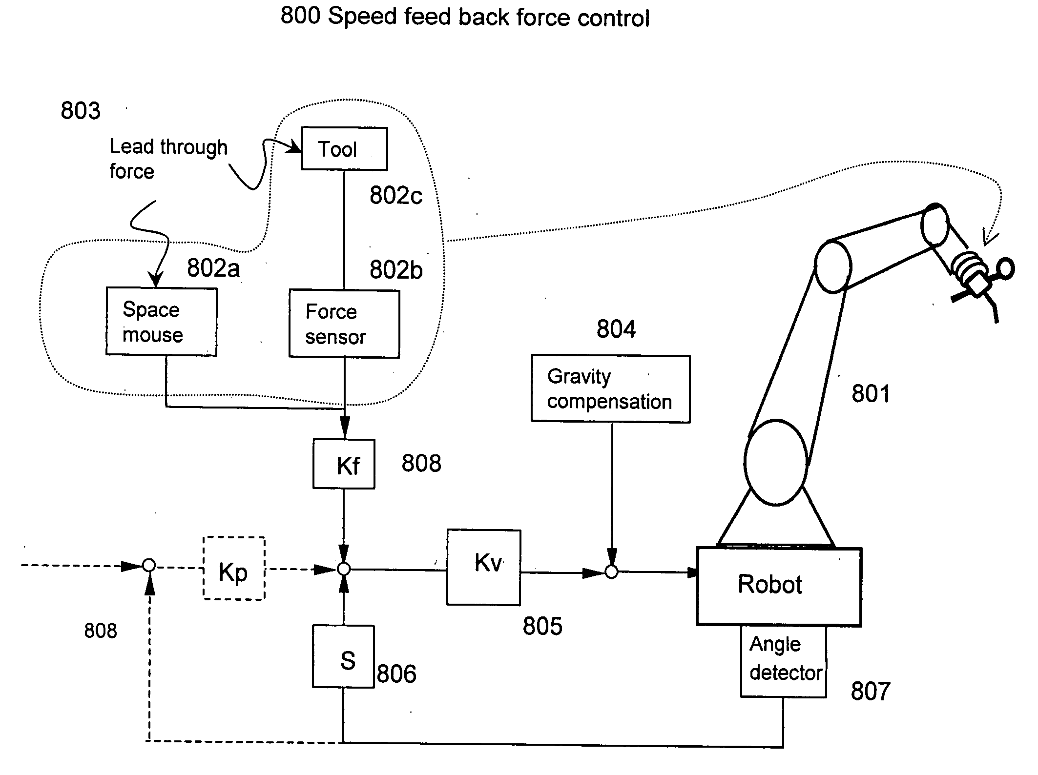
[0041] 3. combination of force sensor and space mouse lead-through teaching;
[0042] 4. translation and orientation portion scaling for lead-through teaching;
[0043] 5. a fast clamping system design and implementation.
The Lead-Through Handle Assembly
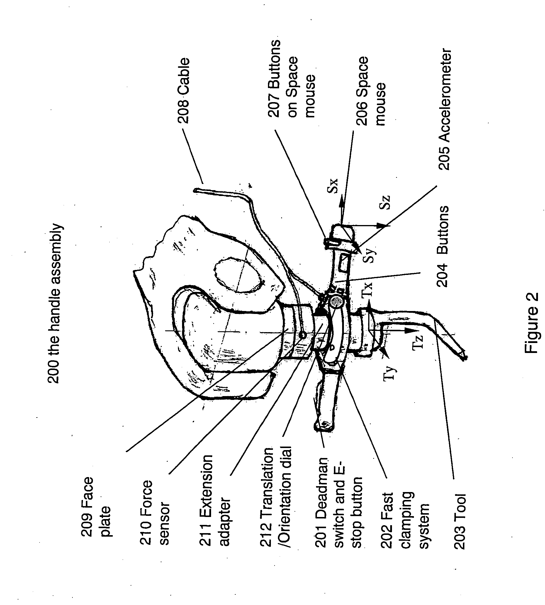
[0044] The lead-through handle assembly 200 is shown in FIG. 2 and includes: a) a three-position deadman switch and E-stop button ...
PUM
 Abstract
Description
Claims
Application Information