Electrified ceiling grid

a ceiling grid and electrical technology, applied in the direction of conductors, flooring, coupling device connections, etc., can solve the problems of increasing the consumption of low voltage electrical power, consuming appreciable electric power in a standby mode, and individual power supplies located at the site or integrated in an electronic device, etc., to achieve the effect of facilitating practical and versatile us

Active Publication Date: 2010-05-27
USG INTERIORS INC
View PDF37 Cites 9 Cited by
  • Summary
  • Abstract
  • Description
  • Claims
  • Application Information

AI Technical Summary

Benefits of technology

[0007]The invention permits and augments the practical and versatile use of the grid elements of a conventional style suspended ceiling to supply and distribute low voltage electrical power to the area of a building with which it is associated. In accordance with the invention, a grid runner or tee of generally conventional cross-sectional shape is employed as a rigid carrier for one or more pair of conductors or as a conductor or conductors itself.

Problems solved by technology

As the use of electronics grows, the consumption of low voltage electrical power likewise grows.
Individual power supplies located at the site of or integrated in an electronic device, the most frequent arrangements today, are often quite inefficient in transforming the relatively high voltage AC utility power to a lower DC voltage required by an electronic device.
Typically, they can consume appreciable electric power in a standby mode when the associated electronic device is shut off.

Method used


Image

  • Electrified ceiling grid
  • Electrified ceiling grid
  • Electrified ceiling grid

Examples


Embodiment Construction

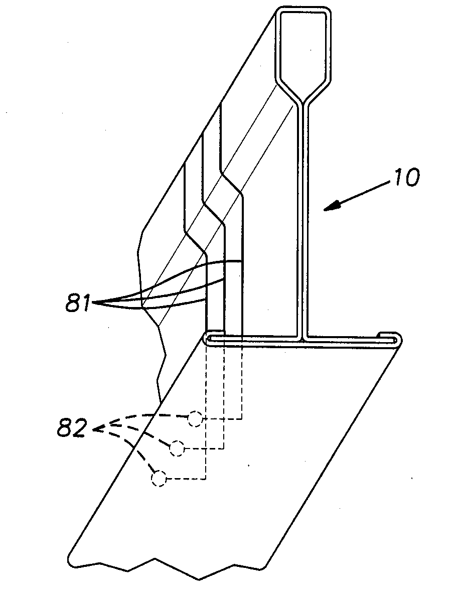
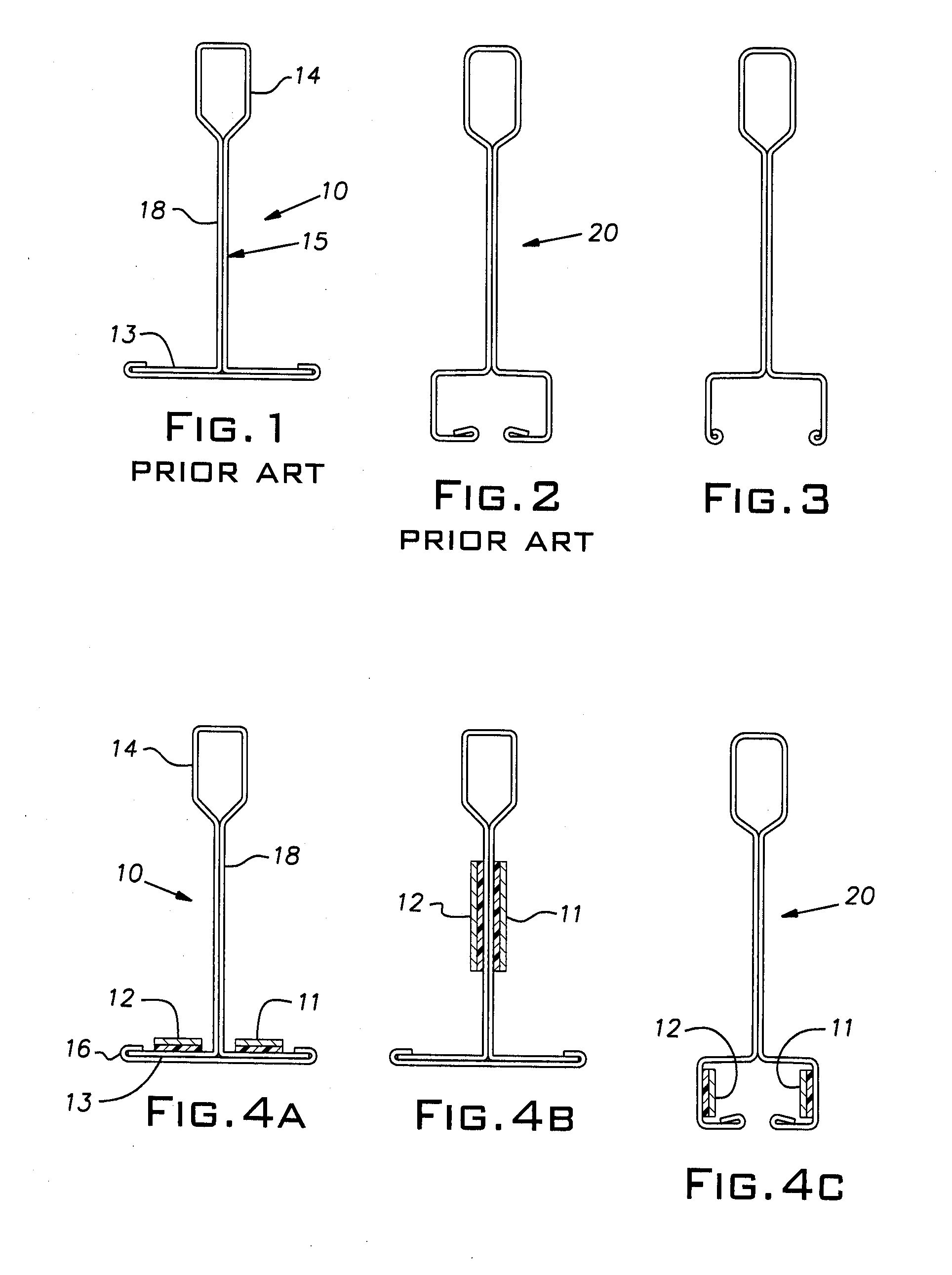
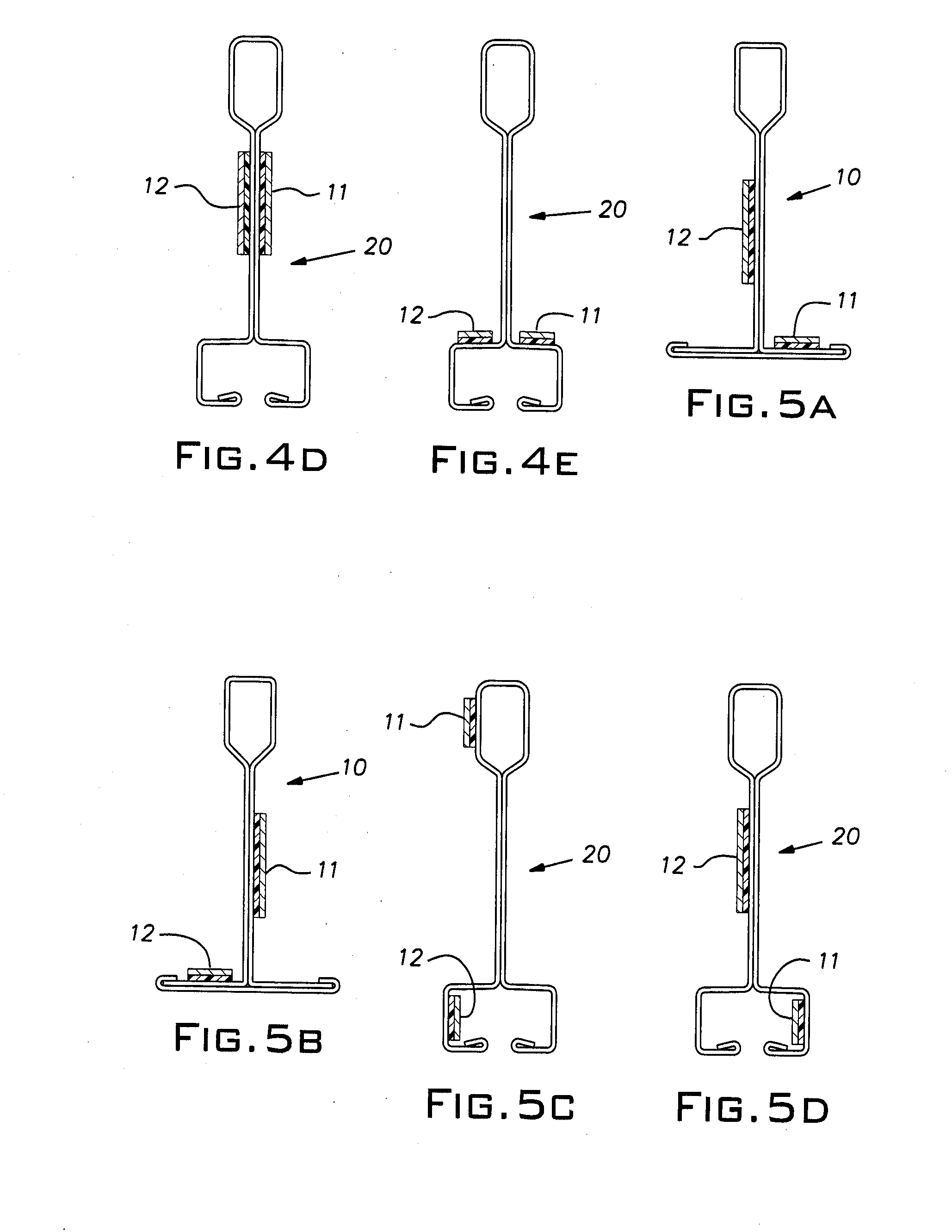
[0026]In FIG. 4A, discrete electrical conductors 11, 12 are fixed to the upper sides of a flange 13 of a grid runner or tee 10 of conventional cross-section. The numeral designation 10 will be used throughout the following disclosure when reference is made to a grid tee of standard configuration. As is customary, the structural body or mass of the tee 10 is roll-formed from metal sheet stock, typically steel. The tee cross-section includes an upper hollow reinforcing bulb 14 and a separate cap 16 folded at its edges over flange elements diverging from a double layer stem 18 extending up to the bulb 14, as is customary. The separate strips forming the tee proper and the cap can be prepainted or coated with a protective film before they are rolled to their finished shape. The conductors 11, 12 in this and other embodiments can take various forms including strips of conductive ink, metal foil, or tape of copper, brass, or aluminum, for example, or single or multi-strand wire running lo...


PUM

PropertyMeasurementUnit
lengthaaaaaaaaaa
conductiveaaaaaaaaaa
symmetryaaaaaaaaaa

Abstract

An elongated grid tee for supplying low voltage power on a suspended ceiling comprising at least two electrically conductive paths electrically insulated from each other, extending lengthwise of the tee, and accessible for receiving or supplying electrical power at numerous locations along the length of the tee.

Description

[0001]This application claims the priority of U.S. Provisional Application No. 61 / 118,058, filed Nov. 26, 2008.BACKGROUND OF THE INVENTION[0002]The invention relates to suspended ceiling structures and, in particular, to electrification of such ceiling structures.PRIOR ART[0003]Commercial building spaces such as offices, laboratories, light manufacturing facilities, health facilities, meeting and banquet hall facilities, educational facilities, common areas in hotels, apartments, retirement homes, retail stores, restaurants and the like are commonly constructed with suspended ceilings. These suspended ceiling installations are ubiquitous, owing to their many recognized benefits. Such ceilings ordinarily comprise a rectangular open grid suspended by wire from a superstructure and tile or panels carried by the grid and enclosing the open spaces between the grid elements. The most common form of grid elements has an inverted T-shaped cross-section. The T-shape often includes a hollow b...

Claims


Application Information

Patent Timeline
Patent Type & Authority Applications(United States)
IPC IPC(8): E04C2/30H01B5/00
CPCE04B9/064H01R25/147E04B9/244E04B9/068
Inventor BOSS, DANIEL
Owner USG INTERIORS INC
Why Eureka
Try Eureka