Illuminating apparatus, image reading apparatus, and image forming apparatus

Active Publication Date: 2011-11-10
SHARP KK
View PDF13 Cites 3 Cited by
  • Summary
  • Abstract
  • Description
  • Claims
  • Application Information

AI Technical Summary

Benefits of technology

[0044]As described above, with the illuminating apparatus, the image reading apparatus and the image forming apparatus of the present invention, since the light-emitting element pitch P and the optical axis distance H are set so as to satisfy the relation M≦N/2−5.5 (limit range in which uneven illuminance is acceptable), it is possible to achieve an optimal relationship between the light-emitting element pitch P and the optical axis distance H, in the state in which uneven illuminance on the light-irra

Problems solved by technology

Thus, it is difficult to say that an optimal relationship can be achieved between the pitch P and the distance H such that light from the light-emitting elements is efficiently irradiated onto the light-irradiated face of

Method used


Image

  • Illuminating apparatus, image reading apparatus, and image forming apparatus
  • Illuminating apparatus, image reading apparatus, and image forming apparatus
  • Illuminating apparatus, image reading apparatus, and image forming apparatus

Examples


Embodiment Construction

[0064]An embodiment of the present invention will be described below with reference to the drawings. Note that the following embodiments are examples of embodying the invention, and do not limit the technical scope of the invention.

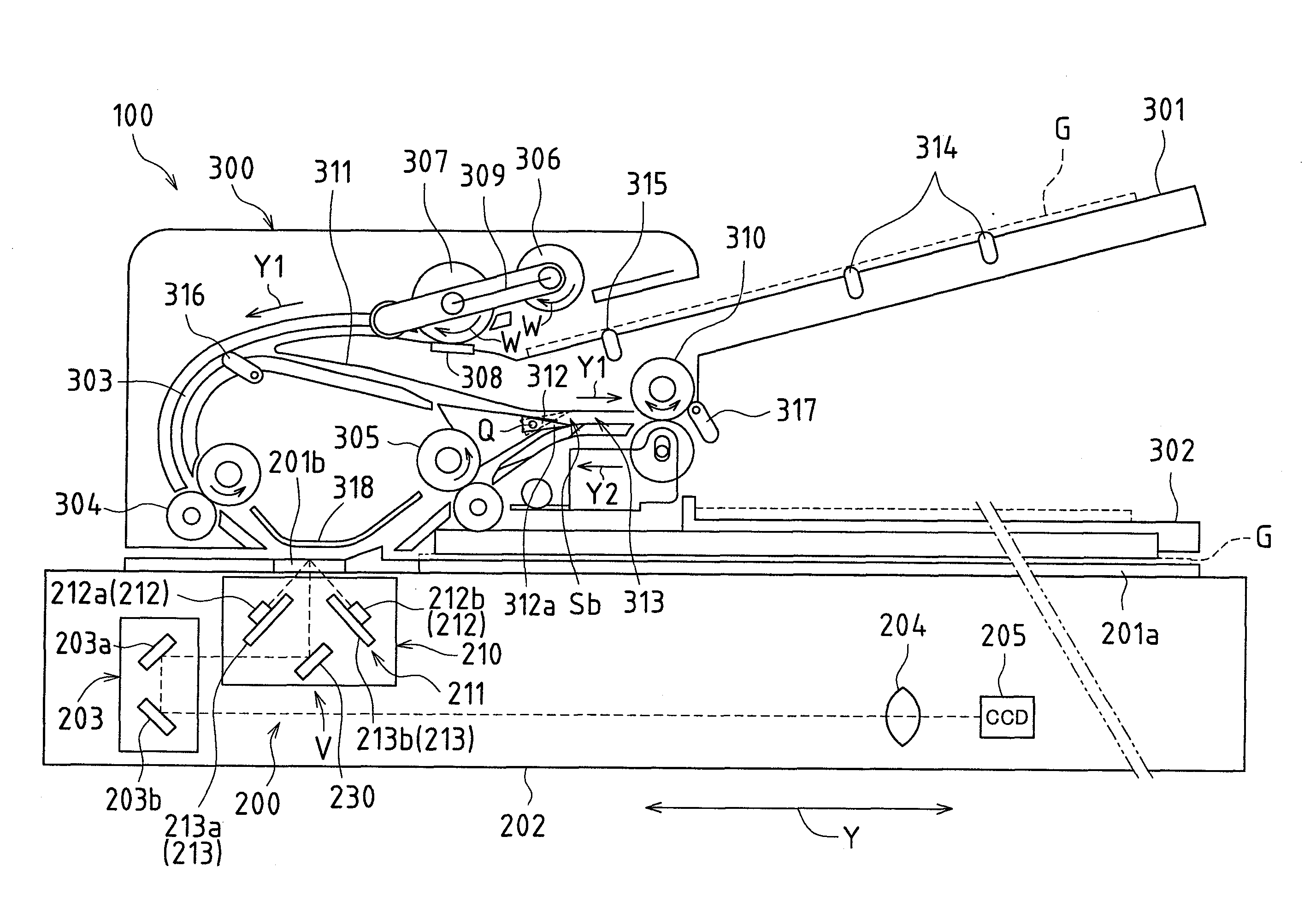
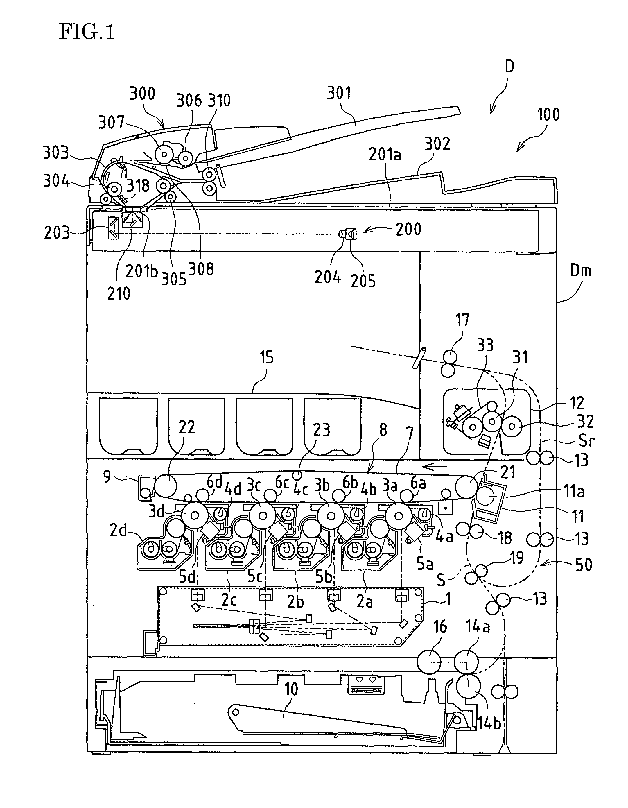
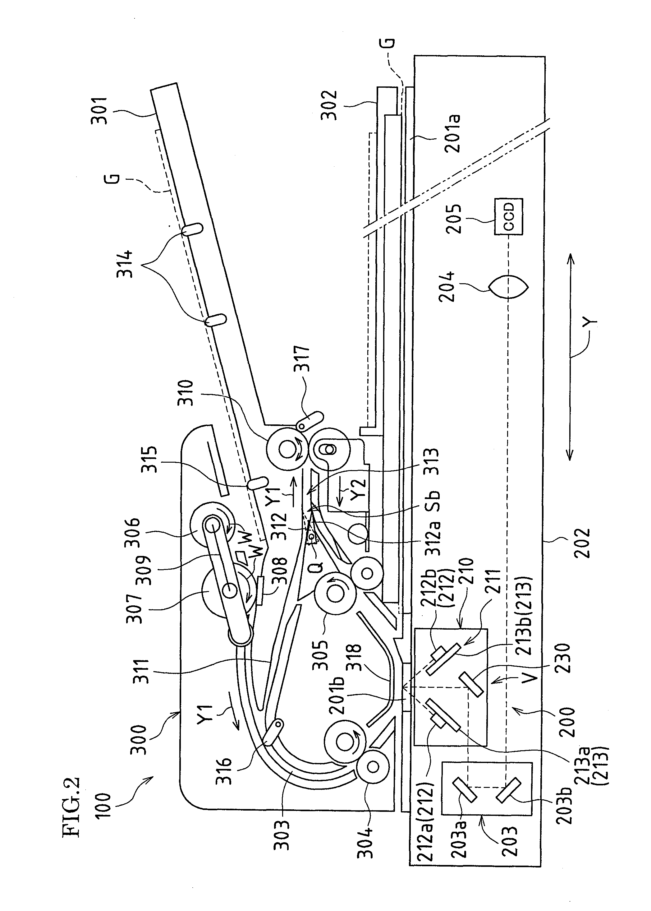
[0065]FIG. 1 is a side view schematically showing an image forming apparatus D provided with an image reading apparatus 100 to which an illuminating apparatus according to an embodiment of the present embodiment is applied.

[0066]The image forming apparatus D shown in FIG. 1 is provided with the image reading apparatus 100, which reads an image of an original G (see FIG. 2 or the like to be described later) and an apparatus main body Dm, which records and forms the image on the original G read by the image reading apparatus 100 or images received from the outside source in color or in monochrome on a recording sheet such as plain paper.

Overall Configuration of Image Forming Apparatus

[0067]The apparatus main body Dm of the image forming apparatus D includes...


PUM


Abstract

In a light source unit (210) serving as an embodiment of an illuminating apparatus, when P is a light-emitting element pitch [mm], and H is an optical axis distance [mm] between light-emitting elements (212) and an original (G), and when, in an illuminance cycle (T) representing repetition of bright and dark areas in a main scanning direction (X) on a light-irradiated face (Gs) of the original (G) caused by the light-emitting elements (212), the light-emitting element pitch (P) and the optical axis distance (H) are set such that unevenness [%] (M) (=(L1−L2)/L3 [%]) obtained by dividing a value obtained by subtracting a minimum illuminance value (L2) from a maximum illuminance value (L1) by an average illuminance value (L3) and an inter-unevenness distance [mm] (N) which is a half cycle of the illuminance cycle (T) satisfy the relation M≦N/2−5.5, and more preferably, M≦N/2−7.5.

Description

TECHNICAL FIELD[0001]The present invention relates to an illuminating apparatus that illuminates an original, an image reading apparatus and an image forming apparatus.BACKGROUND ART[0002]Generally, in image reading apparatuses provided in image forming apparatuses such as copiers, fax machines or digital multi-functional peripherals, or image reading apparatuses connected to a computer via communication means such as a network, light reflected from an original that is illuminated by an illuminating apparatus including a light source is read as the original image.[0003]For example, a conventional image reading apparatus includes an illuminating apparatus in which a light source for illuminating an original placed on a platen glass and a first mirror are arranged, second and third mirrors, an imaging lens and an imaging element (for example, a line sensor such as a CCD (Charge Coupled Device)). Many of such image reading apparatuses are configured to read an original image by causing...

Claims


Application Information

Patent Timeline
IPC IPC(8): H04N1/04F21S4/00
CPCG03B27/54G03G15/043H04N1/02815H04N2201/0081H04N1/02865H04N1/1013H04N1/193H04N1/02845
Inventor SUTO, YASUHIROOKADA, TOMOHIKOFUKUTOME, SHOHICHIYAMANAKA, HISASHINAKANISHI, KENJIYAMADA, YOSHIHISAYOSHIMOTO, MITSUHARUKURIMOTO, EIJISAKAI, KEIJI
Owner SHARP KK
Why Eureka
Try Eureka