Cantilevered wing wall

a technology of cantilevering and wing wall, which is applied in the field of cantilevering concrete retaining walls, can solve the problems of retaining wall base sliding outward, retaining wall tilting forward, and poor quality of soil, and achieves the effects of less susceptible to failure, cost-effective fabrication, and flexible us

Active Publication Date: 2015-04-30
OLDCASTLE PRECAST
View PDF4 Cites 5 Cited by
  • Summary
  • Abstract
  • Description
  • Claims
  • Application Information

AI Technical Summary

Benefits of technology

[0005]In view of the limitations in prior art retaining walls and methods of using them, the present disclosure provides a new and useful precast cantilevered wing wall and a method of use thereof which is cost effective to fabricate, more versatile in use than known prior art retaining walls, and less susceptible to failure.

Problems solved by technology

Retaining walls are subject to various forces that may cause them to fail.
Pressure at the toe of the footing is generally larger than pressure at the heel of the footing so retaining walls have an inherent tendency to tilt forward away from an embankment.
Occasionally, the base soil is of a poor quality and when sufficient backfill is placed between the backface of the retaining wall and an embankment, for example, the approach fill at a bridge abutment, the backfill pressure produces a settlement with lateral effect into the zone beneath the heel so that the retaining wall may tilt back into the backfill and the embankment.
Lateral forces generated by earth and water pressure may cause the base of the retaining wall to slide outward and fail.
Some soil types are more prone to shifting or erosion and may decrease the friction between the footing and soil.
However, making the footing wider increases the amount of materials used, increases transportation costs, and requires increased excavation of soil to form a wider subgrade which increases cost and time required for site preparation and installation.
In some cases, it may not be possible to increase the footing width based on site requirements.
The depth of the footing cover can also be increased in some situations to provide additional resistance to lateral forces; however, this also increases the cost of site preparation because excavation must be deeper, and additional concrete is required which increases costs as well.
Creating forms for a retaining wall at a job site is time consuming and may require the presence of many employees at a remote location.
The job site may not be as safe for employees as a precast plant due to open excavations, the presence of heavy equipment, and the natural environment.
The forms may have to be custom made, increasing labor and material costs and making re-use of the forms unlikely.
Placing and aligning reinforcing steel precisely at a job site may be more difficult than at a precast plant, potentially weakening the retaining wall.
The concrete for the retaining walls may have to be transported long distances to the job site in individual truckloads increasing transportation and labor costs.
Finally, the concrete is exposed to the environment while it is curing which can increase the curing time or adversely affect the strength characteristics of the retaining wall.
Construction of the project may be delayed while waiting for the concrete to cure.
Due to the numerous limitations associated with cast-in-place retaining walls, there is an unmet need for a precast concrete retaining wall which has a coefficient of friction equivalent to a cast-in-place retaining wall of similar size.

Method used


Image

  • Cantilevered wing wall
  • Cantilevered wing wall
  • Cantilevered wing wall

Examples


Embodiment Construction

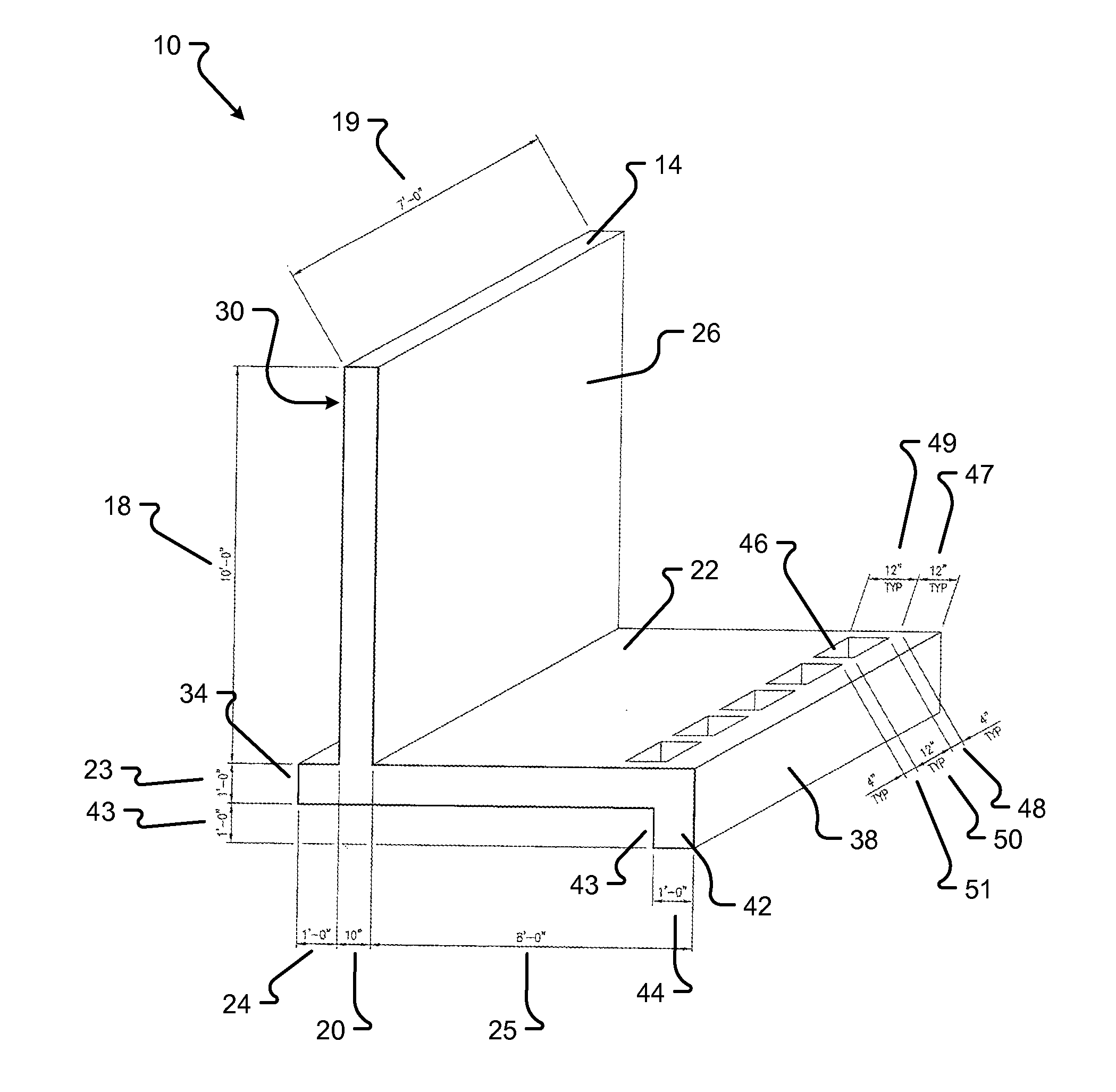
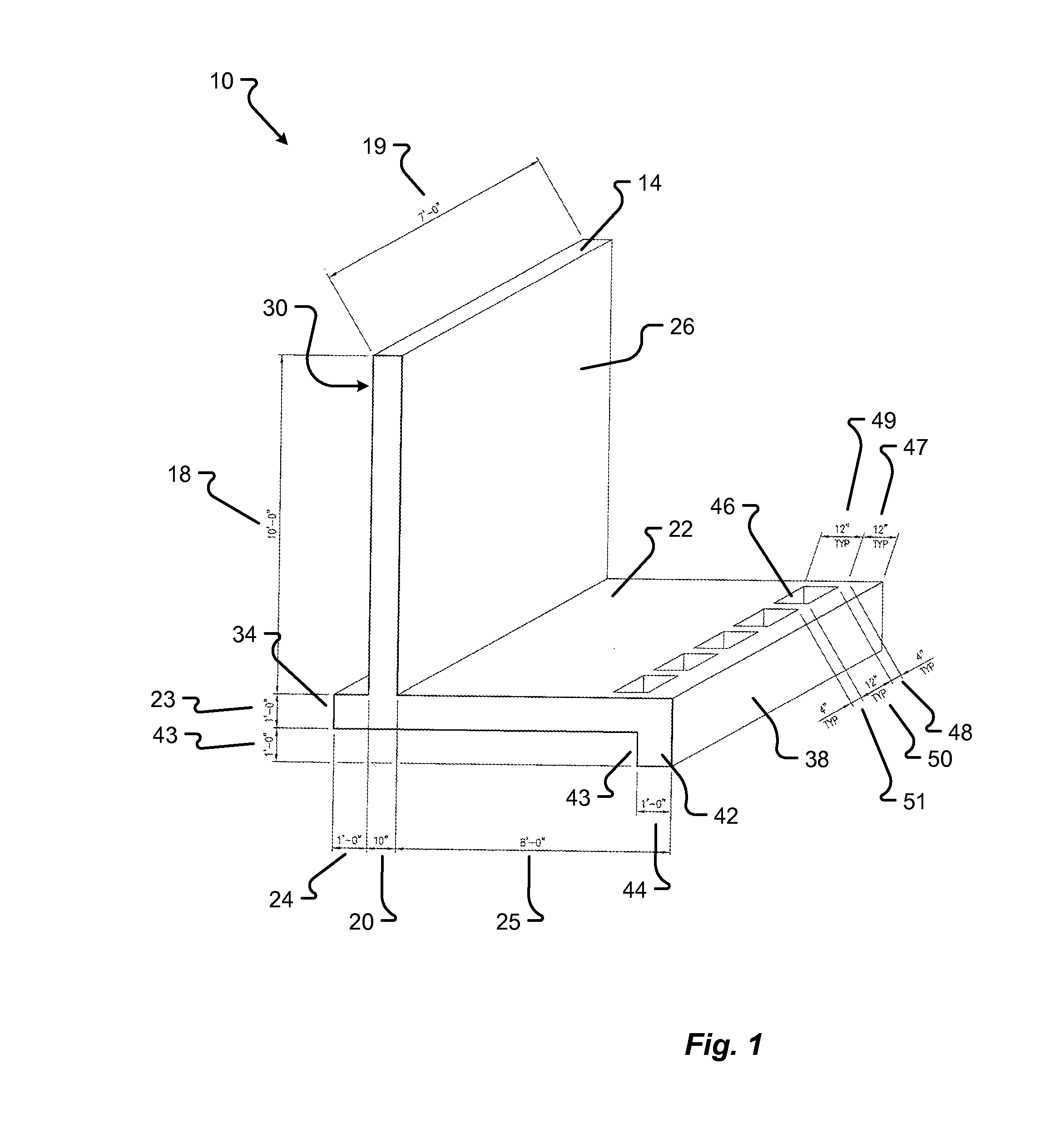
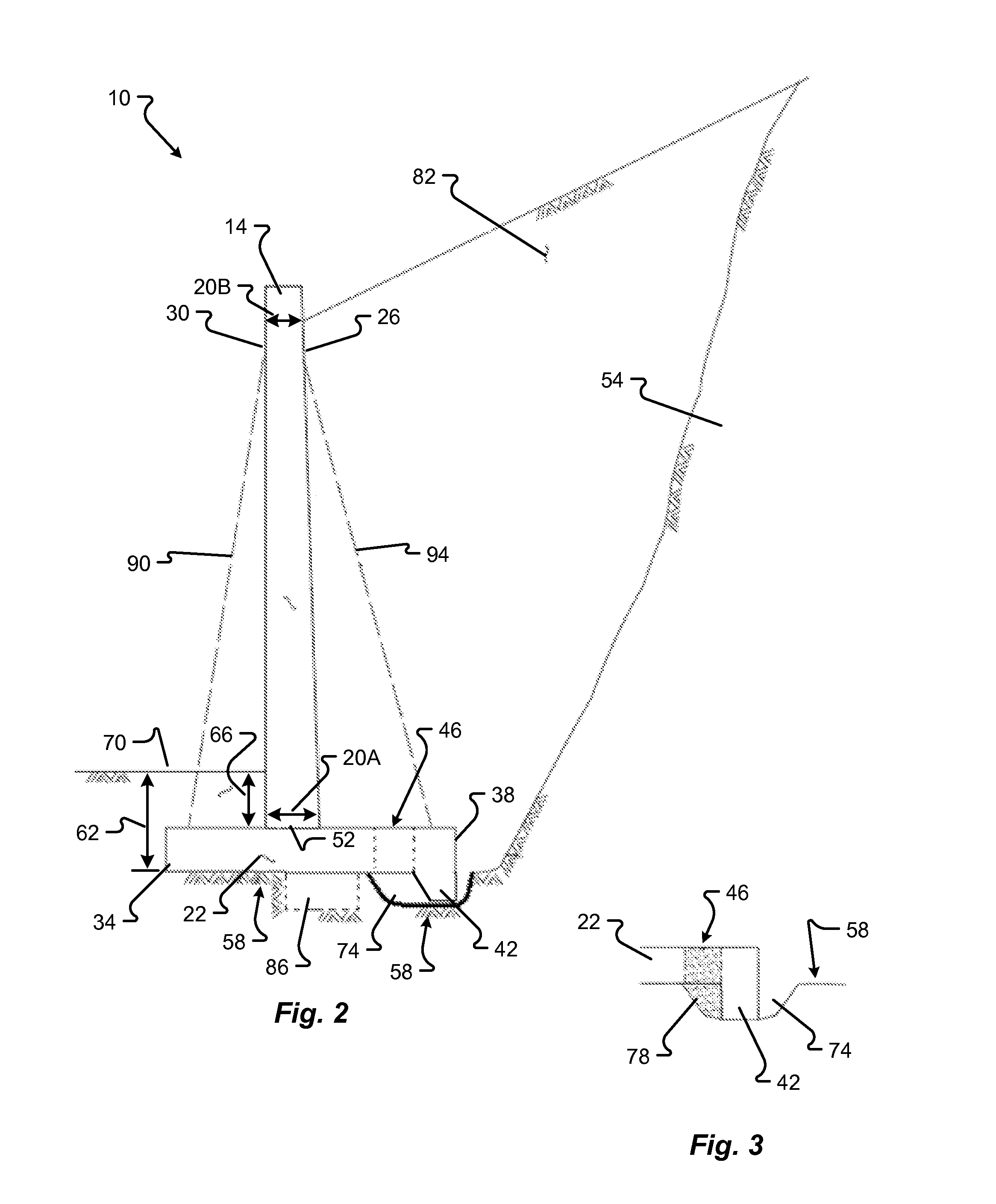
[0034]Various embodiments of the present invention are described herein and as depicted in the drawings. The present disclosure has significant benefits across a broad spectrum of endeavors. It is the applicant's intent that this specification and the claims appended hereto be accorded a breadth in keeping with the scope and spirit of the invention being disclosed despite what might appear to be limiting language imposed by the requirements of referring to the specific examples disclosed. It is expressly understood that although FIGS. 1-6 depict embodiments of precast cantilevered wing walls, the present invention is not limited to these embodiments and may be used in any form of application related to retaining walls or systems and methods to prevent the inadvertent movement of soil.

[0035]Referring now to FIG. 1, an embodiment of a precast cantilevered wing wall 10 of the present invention is shown. In the example of FIG. 1, the cantilevered wing wall 10 includes a stem 14 having a...


PUM

PropertyMeasurementUnit
widthaaaaaaaaaa
depthaaaaaaaaaa
depthaaaaaaaaaa

Abstract

The present invention relates generally to precast cantilevered retaining walls. More specifically, the present invention relates to a cantilevered concrete retaining wall having a base shear key and blockouts for receiving a material that substantially impedes the wing wall from sliding or other inadvertent movement.

Description

FIELD OF THE INVENTION[0001]The present invention relates generally to precast cantilevered retaining walls. More specifically, the present invention relates to a cantilevered concrete retaining wall having a base shear key and blockouts for receiving a material that substantially impedes the wing wall from sliding or other inadvertent movement.BACKGROUND[0002]Retaining walls are subject to various forces that may cause them to fail. Pressure at the toe of the footing is generally larger than pressure at the heel of the footing so retaining walls have an inherent tendency to tilt forward away from an embankment. Occasionally, the base soil is of a poor quality and when sufficient backfill is placed between the backface of the retaining wall and an embankment, for example, the approach fill at a bridge abutment, the backfill pressure produces a settlement with lateral effect into the zone beneath the heel so that the retaining wall may tilt back into the backfill and the embankment. ...

Claims


Application Information

Patent Timeline
Patent Type & Authority Applications(United States)
IPC IPC(8): E02D29/02
CPCE02D29/0275B28B1/14E02D29/0266
Inventor HIESTER, STEVEN C.
Owner OLDCASTLE PRECAST
Why Eureka
Try Eureka