Structure of candle holder

a candle holder and shape technology, applied in semiconductor devices for light sources, lighting and heating apparatus, lighting applications, etc., can solve the problems of difficult dynamic variation and insufficient shining effect, and achieve the effect of improving practical use, more dazzling and bright, and being versatile in us

Inactive Publication Date: 2013-01-17
LEE SHENG SHUI
View PDF2 Cites 2 Cited by
  • Summary
  • Abstract
  • Description
  • Claims
  • Application Information

AI Technical Summary

Benefits of technology

[0003]An objective of the present invention is to provide a candle holder that, besides the flame light generated by the candle itself, provides static or dynamic dazzling or flashing light through a main body of the candle holder, whereby thought a combination of the two types of light, the lighting generated by the candle holder is made more dazzling and brighter.
[0004]Another objective of the present invention is to provide a candle holder, wherein even through the candle is not set in fire and burning, the main body of the candle holder may be operated to give off static or dynamic dazzling or flashing of light to make the candle holder versatile in use.
[0005]To achieve the above objective, the present invention provides a candle holder that comprises a main body having a top opening and receiving therein a candle having a wick. The main body has an outer surface to which an optic fiber fabric is attached. The optic fiber fabric comprises a base plate and a woven sheet of optic fibers that is connected to a controller and an LED lamp. The LED lamp emits a light source that makes the woven sheet of optic fibers giving off light on a whole surface thereof or dazzling or flashing of light, whereby the candle holder, besides the candle light, provides an additional function of showing a bright and sparkling appearance to improve the practical use thereof.

Problems solved by technology

Although this structure of candle holder makes a significant progress over the traditional candle holder for providing a more shining lighting effect, yet the lighting effect all comes from the flame light emitting from the burning wick, which is quite static and monotonous, making it hard to provide dynamic variation.
Consequently, the shining effect is not good enough.

Method used


Image

  • Structure of candle holder
  • Structure of candle holder
  • Structure of candle holder

Examples


Embodiment Construction

[0012]The following descriptions are exemplary embodiments only, and are not intended to limit the scope, applicability or configuration of the invention in any way. Rather, the following description provides a convenient illustration for implementing exemplary embodiments of the invention. Various changes to the described embodiments may be made in the function and arrangement of the elements described without departing from the scope of the invention as set forth in the appended claims.

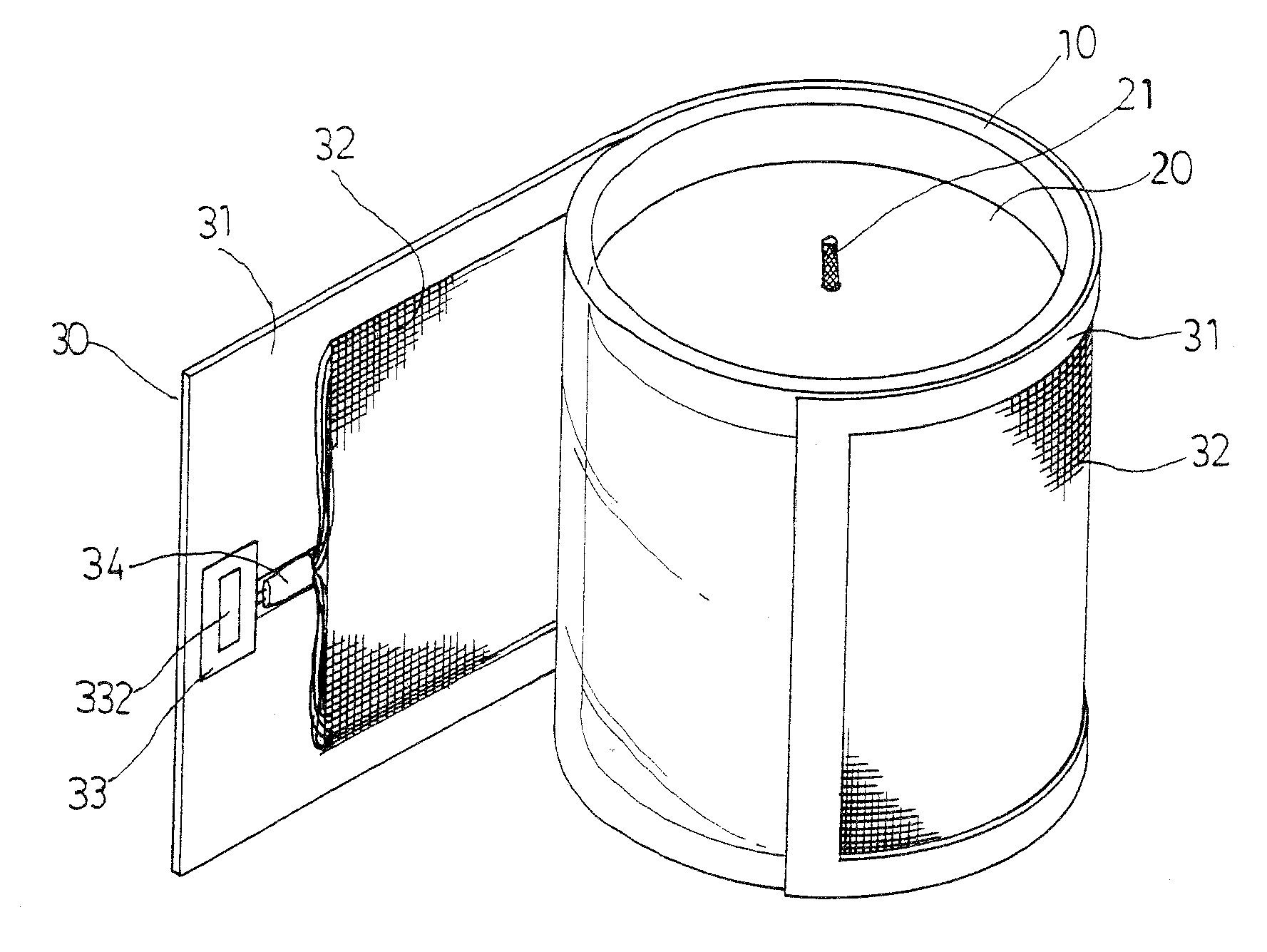
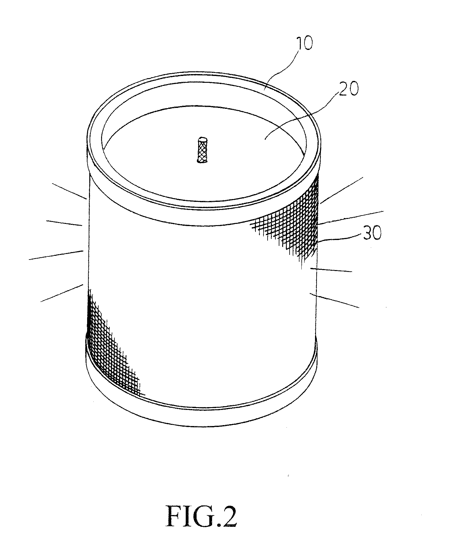
[0013]As shown in FIGS. 2 and 3, the present invention provides an improved structure of candle holder, which comprises a main body (10), a candle (20), and a piece of optic fiber fabric (30). The main body (10), which is preferably light transmitting, is structured to show an arbitrary shape having a top opening. The candle (20), which is preferably made light-transmitting, is received in the main body (10), preferably by pouring wax, paraffin or similar materials therein, and comprises a wick (21)...


PUM


Abstract

A candle holder includes a main body having a top opening and receiving therein a candle having a wick. The main body has an outer surface to which an optic fiber fabric is attached. The optic fiber fabric includes a base plate and a woven sheet of optic fibers that is connected to a controller and an LED lamp. The LED lamp emits a light source that makes the woven sheet of optic fibers giving off light on a whole surface thereof or dazzling or flashing of light, whereby the candle holder, besides the candle light, provides an additional function of showing a bright and sparkling appearance to improve the practical use thereof.

Description

(a) TECHNICAL FIELD OF THE INVENTION[0001]The present invention generally relates to an improved structure of arbitrarily-shaped candle holder, which, besides the basic function of lighting with candle flame, provides an additional function of dazzling shining appearance to improve the practical use thereof(b) DESCRIPTION OF THE PRIOR ART[0002]A conventional candle holder is illustrated in FIG. 1 of the attached drawings, which has a simple structure comprising a main body (10) that has a top opening and is light transmitting and receives therein a light-transmitting candle (20). The candle (20) comprises a wick (21), which has an upper end exposed outside a top face of the candle (20) for burning. After being lit, the candle makes a flame that gives off light. The light may transmit through the candle (20), making the circumference of the main body (10) also emitting light, which results in a sparkling and dazzling effect of the candle holder. Although this structure of candle hold...

Claims


Application Information

Patent Timeline
Patent Type & Authority Applications(United States)
IPC IPC(8): F21V33/00F21V11/00
CPCF21V35/00F21S10/06F21Y2101/02F21V23/04F21W2121/00F21S19/00F21Y2115/10
Inventor LEE, SHENG-SHUI
Owner LEE SHENG SHUI
Why Eureka
Try Eureka