[0022]The technique for manufacturing typical embodiments of the stylus tip starts with a base
fiber (preferably a common, inexpensive base
fiber) that is already conducive to felting.
Wool or any other
fiber that has scales which
interlock at the
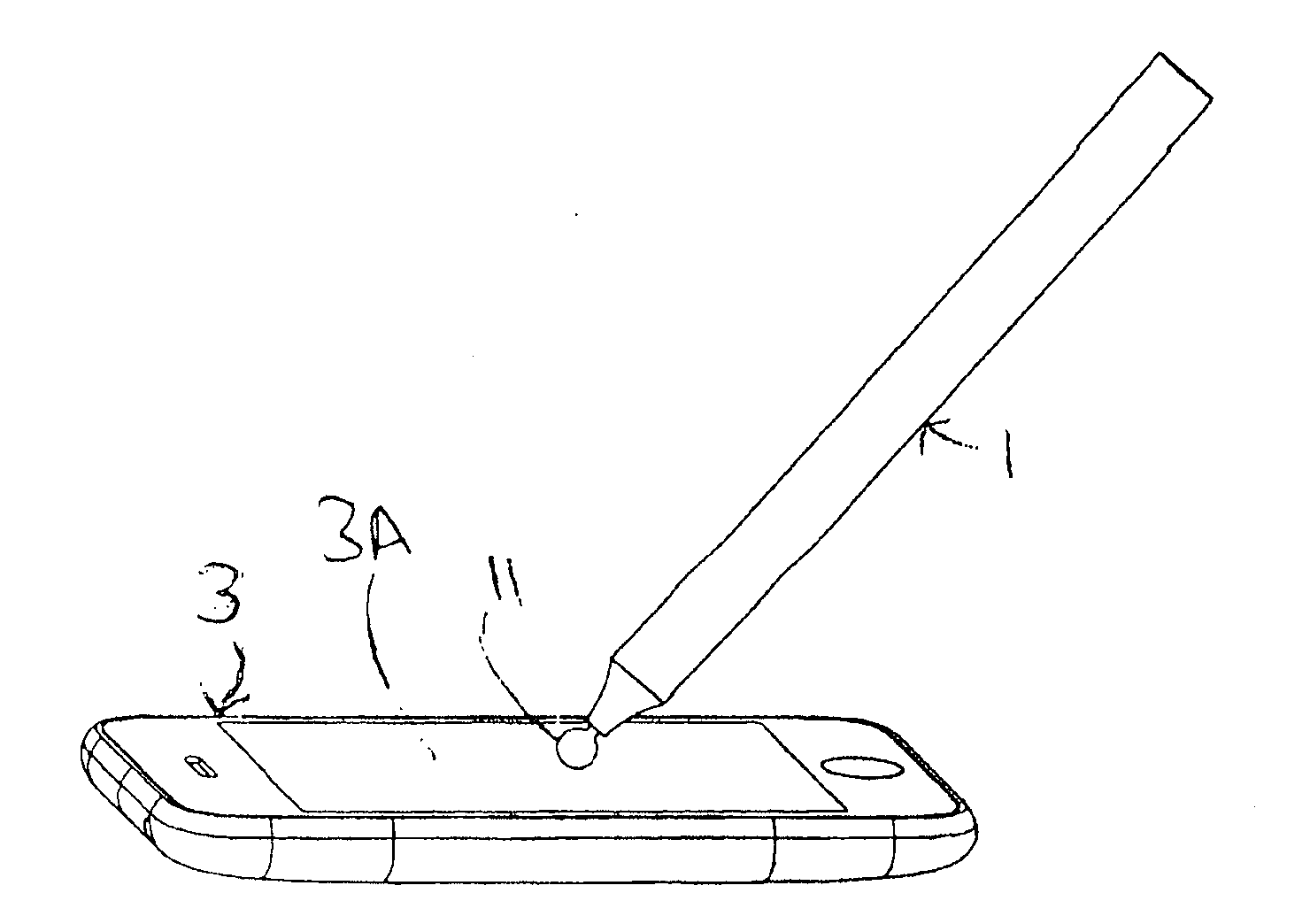
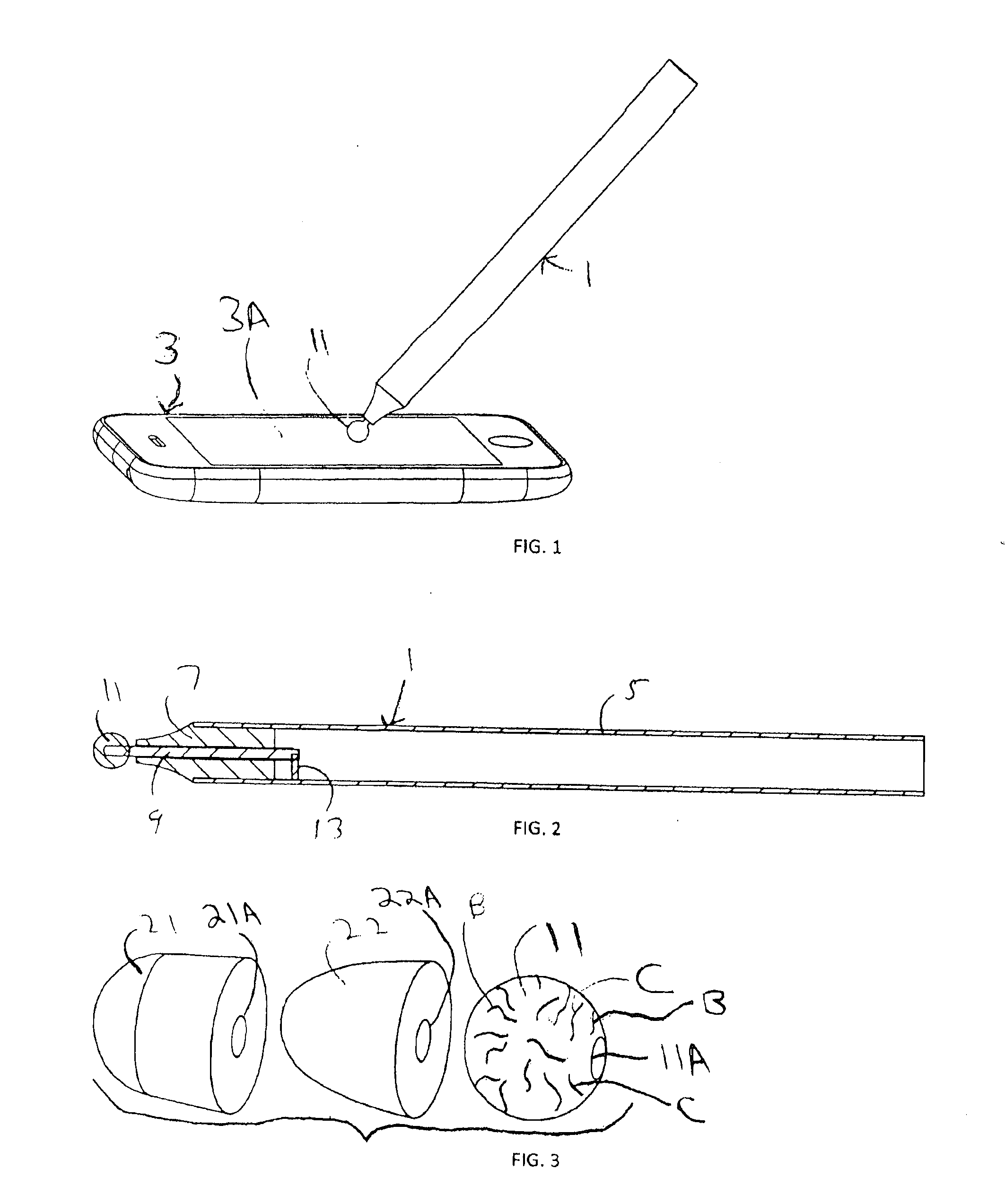
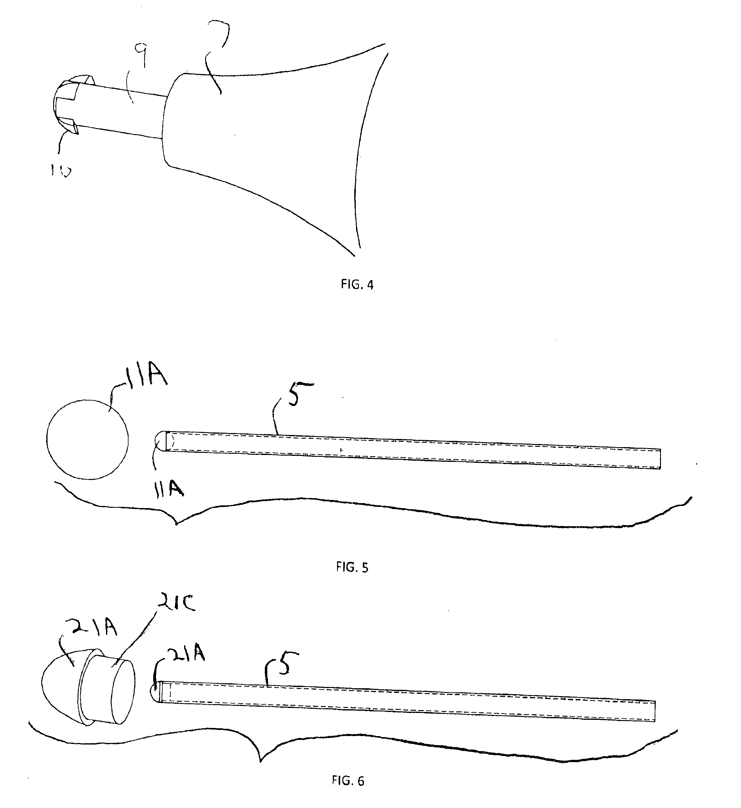
microscopic level during a felting process is suitable as a base fiber in many embodiments. Interspersing this base fibers with conductive fibers, which typically do not have the same microscopic characteristics necessary for felting, allows the base fibers to lock and hold the strands of the conductive fibers. The felting should produce a semi-rigid, felt object having shape suitable for use as the tip of a capacitive touch screen stylus (e.g., spherical, hemispherical or bullet-like shape), and size suitable for affixing to the end of a capacitive touch screen stylus body (e.g., a conductive rod or tube, or a non-conductive tube including or coupled to a capacitance, where the capacitance is connected by a conductor to the felt object in at least one operating mode). When the stylus has a conductive body, the conductive body (and optionally a conductive structure between the felt tip and the conductive body) couples with the human hand and therefore provides a
low impedance path between the conductive
felted tip and the
human body, allowing a capacitive touch screen to properly calculate a
centroid based on the area of contact between the tip and the screen. By using base fibers of sufficiently
low friction (when
felted) in the tip, the
coefficient of friction of the felted tip against the glass surface of a capacitive touch screen is significantly low to allow for a natural (pen-like) feel of the stylus as the tip slides on (or is touched against) the screen.
[0027]The blending percent also depends upon the shape of the final felted product as well as the means by which it is felted or the fibers are otherwise combined prior to needle felting or felting with water. For example, when the fibers are organized such as through knitting, crocheting, braiding, knotting, weaving and / or
spinning into multiple plies, the conductive properties are reduced, thereby requiring a higher percentage of conductive fiber in the felting mix. When using a mixture of 50% conductive fibers and 50% base fibers (by weight), one can knit an I-cord (a spiral knit tube also called idiot cord) to make a tip with the necessary conductive properties. By knitting the I-cord before needle felting or wet felting, the fibers are pre-tangled before felting, resulting in a tip that holds its shape over use with time. When a tip is
cut from either end of a felted I-cord, the tip has a bullet shape with a rounded end that is finished and will not splay, unravel, or wear as quickly with use as a tip that is made from a
cut end of
yarn that has been needle felted and wet felted.
[0047]Audio signals generated by a host (e.g., comprising frequency components of multiple frequencies that are mixed together, or pulse trains) can be asserted via an audio cable to the stylus. These signals can be returned (looped back, with optional attenuation) to the host, or not returned to the host, depending on the state of passive switched circuitry in the stylus. For example, signals asserted to the stylus on left and right audio channels could have different frequency content (e.g., one could comprise frequency components in a first band; the other comprising frequency components in a different band) for easier discrimination
processing (by the host) of signals returned to the host from the stylus.
[0059]In some embodiments, the invention is a capacitive touch screen device that is configured to recognize (e.g., includes a processor programmed to recognize) an operating mode of an embodiment of the inventive stylus in response to at least one
signal indicative of the state of switching circuitry in the stylus, and in response to touch screen sensor data (i.e., data generated and processed conventionally in touch screen devices to calculate a
centroid from an outline of an object's contact area on a touch screen) including by
processing the touch screen sensor data in at least one of the following additional ways beyond the time window method ways: disambiguating movement of the stylus on the screen versus non-stylus strokes by predicting a future location of contact area of the stylus on the screen (e.g., by determining a vector established by the previous sequence of centroids (or other measures of the location) of each previous user strokes of the moving stylus assigned contact areas on the touch screen and establishing a probability that the tip generated
stroke will be coincident with that vector by using a process of
dead reckoning); determining velocity of each segment within the contact
stroke on the screen and using a threshold to eliminate all strokes that contain segments that exceed a certain threshold velocity; determining acceleration of each segment within the contact stroke on the screen and establishing a probability that the stroke is intended or spurious using mathematical functions of acceleration; determining the acceleration between the end of the previously classified tip stroke and the beginning of the current stroke and establishing a probability that the stroke is intended or spurious using mathematical functions of acceleration; determining a measure of the location of currently active “palm” strokes classified by previous
processing (e.g., by assuming all non-tip strokes must be palm strokes) and using the relative locations of these active palm strokes to create a probability that the unclassified stroke is intended or spurious using a mathematical function of the distance between said palm locations and the unclassified stroke. In the absence of
prior information (i.e., first touch, or a touch that occurs after a certain time threshold, and no currently active palm location), the method establishes a probability that each stroke is generated by a stylus or palm based on a function (e.g., median, mean or median
absolute deviation from the median) of the length of segments in the stroke. These techniques alone or in combination can allow (or help to allow) the touch screen device to disambiguate between user-intended stylus touches on the screen and non-intended or spurious “palm” touches.

