
Method and apparatus for selective control of nerve fibers

a nerve fiber and selective control technology, applied in the field of nerve fiber selective control, can solve the problems of limited effectiveness of pain control techniques, severe discomfort or distress, and the number of side effects of the most commonly prescribed narcotics, and achieve the effects of reducing other sensations, reducing pain sensations, and reducing pain sensations

Inactive Publication Date: 2003-07-29
MEDTRONIC INC
View PDF3 Cites 492 Cited by
  • Summary
  • Abstract
  • Description
  • Claims
  • Application Information

AI Technical Summary

Benefits of technology

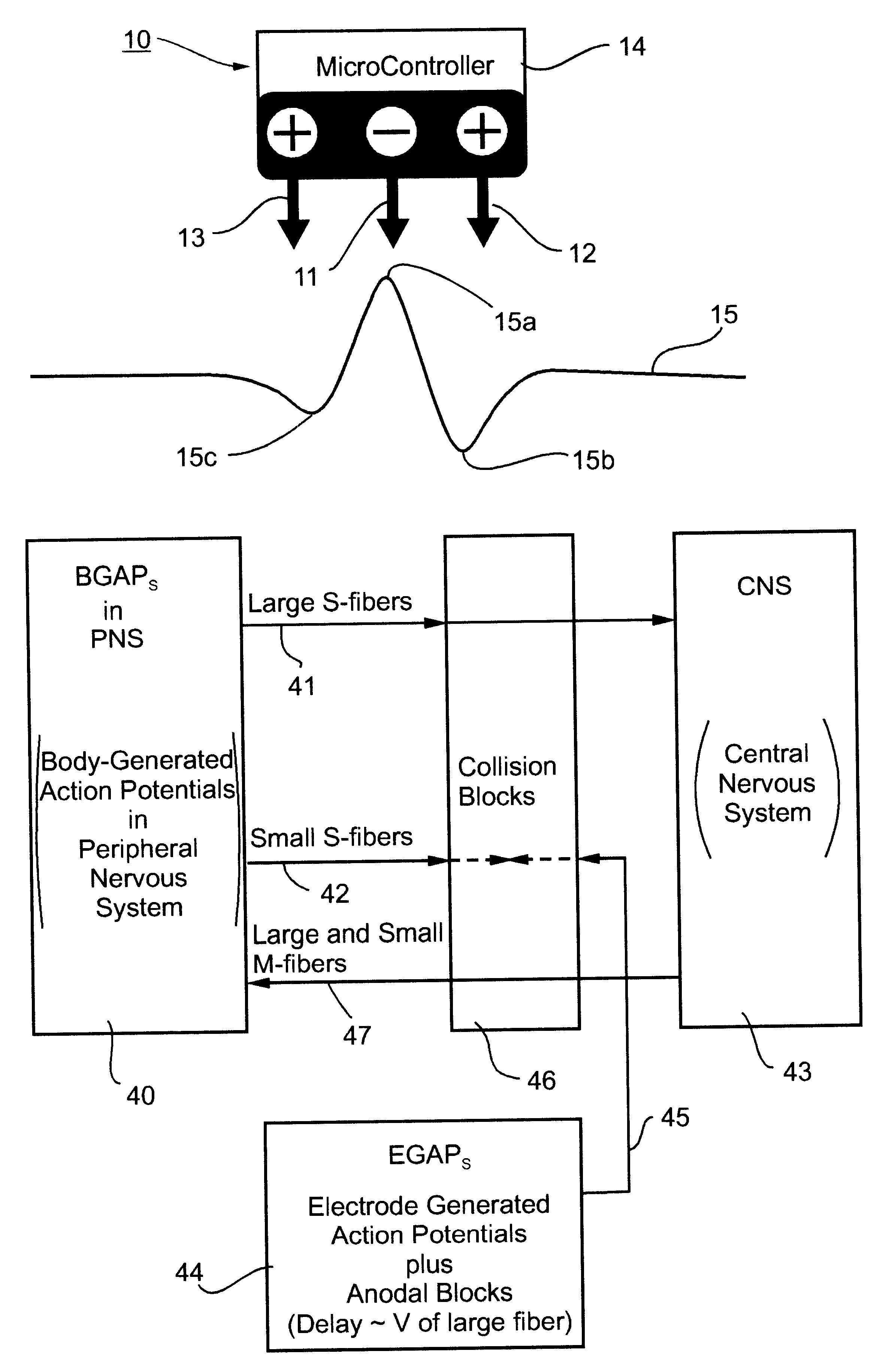
According to one aspect of the present invention, there is provided a method of reducing pain sensations resulting from the propagation of body-generated action potentials towards the central nervous system through small-diameter sensory fibers in a nerve bundle, without unduly reducing other sensations resulting from the propagation of body-generated action potentials towards the central nervous system through large-diameter sensory fibers in the nerve bundle, comprising: applying to the nerve bundle at least one electrode device capable, upon actuation, of generating unidirectional action potentials to be propagated through both the small-diameter and large-diameter sensory fibers in the nerve bundle away from the central nervous system; and actuating the electrode device to generate the unidirectional action potentials to produce collision blocks with respect to the body-generated action potentials propagated through the small-diameter fibers.
Preferably, this aspect of the invention utilizes the tripolar electrode devices described, for example, in the above-cited publications, except that, instead of using such tripolar electrodes for producing collision blocks of action potentials travelling through motor nerves away from the central nervous system in order to control muscular or glandular activity, there are used to produce collision blocks of action potentials propagated through sensory nerves towards the central nervous system in order to reduce pain sensations without unduly hindering other sensations.
According to another aspect of the present invention, there is provided a method of selectively suppressing the propagation of of body-generated action potentials propagated in a predetermined direction at a first velocity through a first group of nerve fibers in a nerve bundle without unduly suppressing the propagation of body-generated action potentials propagated in the predetermined direction at a different velocity through a second group of nerve fibers in the nerve bundle, comprising: applying a plurality of electrode devices to, and spaced along the length of, the nerve bundle, each electrode device beams capable of outputting, when actuated, unidirectional electrode-generated action potentials producing collision blocks with respect to the body-generated action potentials propagated through the second type of nerve fibers; and sequentially actuating the electrode devices with delays timed to the first velocity to produce a "green wave" of anodal blocks minimizing undesired blocking of the body-generated action potentials propagated through the first group of nerve fibers while maximizing the generation rate of said unidirectional electrode-generated action potentials producing collision blocks with respect to the body-generated action potentials propagated through said second type of nerve fibers.

Problems solved by technology

However, there are many types of pains which do not serve this useful purpose and can cause severe discomfort or distress.
The narcotics most commonly prescribed not only have a number of worrisome side effects, but are of limited effectiveness for millions of persons who suffer from neuropathic pain arising from damage to the nerves caused by disease, trauma or chemotherapy.
This technique for pain control, however, has had a very limited degree of success.
If sufficiently hyper-polarized, action potentials are not able to propagate through the hyper-polarized zone and will be blocked.

Method used


Image

  • Method and apparatus for selective control of nerve fibers
  • Method and apparatus for selective control of nerve fibers
  • Method and apparatus for selective control of nerve fibers

Examples


Embodiment Construction

The Tripolar Electrode

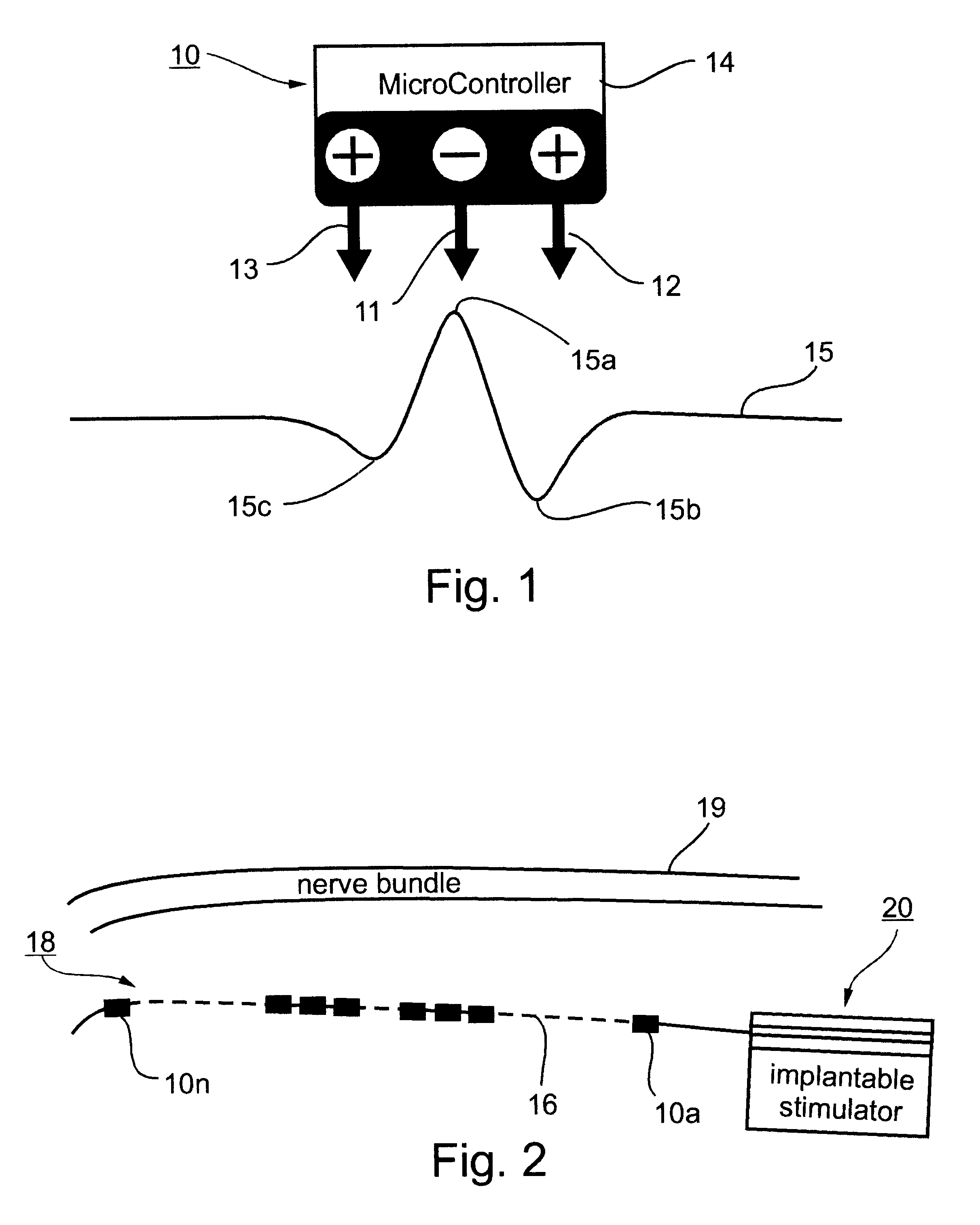
A basic element in the preferred embodiments of the method and apparatus described below is the tripolar electrode device. Its construction and operation are diagrammatically illustrated in FIG. 1.

As shown in FIG. 1, the tripolar electrode device, therein designated 10, includes three electrodes, namely, a central cathode 11, a first anode 12 on one side of the cathode, and a second anode 13 on the opposite side of the cathode. The illustrated tripolar electrode device further includes a microcontroller 14 for controlling the three electrodes 11, 12 and 13, as will be described below.

Curve 15 shown in FIG. 1 illustrates the activation function performed by the tripolar electrode device 10 on the nerve bundle underlying it. As shown in FIG. 1, this activation function includes a sharp positive peak 15a underlying the cathode 11, a relatively deep negative dip 15b underlying the anode 12, and a shallower negative dip 15c underlying the anode 13.

When the tripolar ...


PUM


Abstract

A method and apparatus particularly useful for pain control by selectively blocking the propagation of body-generated action potentials travelling through a nerve bundle by using a tripolar electrode device to generate unidirectional action potentials to serve as collision blocks with the body-generated action potentials representing pain sensations in the small-diameter sensory fibers. In the described preferred embodiments there are a plurality of electrode devices spaced along the length of the nerve bundle which are sequentially actuated with delays corresponding to the velocity of propagation of the body-generated action potentials through the large-diameter fibers to produce a "green wave" effect which minimizes undesired anodal blocking of the large-diameter fibers while maximizing the collision blocking of the small-diameter fibers.

Description

FIELD AND BACKGROUND OF THE INVENTIONThe present invention relates to the selective control of nerve fibers in the human nervous system. The invention is especially useful for selectively blocking sensory nerve fibers for blocking pain sensations while permitting other sensations to pass, and is therefore particularly described below with respect to this application. However, as will also be described below the invention could also be used in other applications, e.g., in selectively blocking motor nerve fibers for controlling muscles or glands.The nervous system is a network of billions of interconnected nerve cells (neurons) that receive various types of stimuli and cause the body to respond appropriately. The individual nerve cells transmit the messages by means of a complicated electrochemical process which generates action potentials transmitted by axons, or nerve fibers. Such nerve fibers link the central nervous system (CNS) consisting of the brain and the spinal cord, with th...

Claims


Application Information

Patent Timeline
Patent Type & Authority Patents(United States)
IPC IPC(8): A61N1/32A61N1/34A61N1/36
CPCA61N1/36071
Inventor COHEN, EHUDAYAL, SHAI
Owner MEDTRONIC INC
Learn More