Vibrating tourniquet

a tourniquet and vibration technology, applied in the field of tourniquets, can solve the problems of pain and anxiety in patients, tissue death in the affected limb, discomfort in the patient, etc., and achieve the effect of reducing the sensation of pain

Inactive Publication Date: 2007-04-19
PERRY ERIC S
View PDF4 Cites 28 Cited by
  • Summary
  • Abstract
  • Description
  • Claims
  • Application Information

AI Technical Summary

Benefits of technology

[0006] The improved tourniquet of the present invention introduces one or more vibrating devices within its pliable strap portion that interrupt nerve transmissions, and supply an alternative stimulus that decreases the sensation of pain as the needle or IV are introduced through the skin and into a vein. The devices contain a controller mechanism that may be turned on or off after the tourniquet is applied to the arm.

Problems solved by technology

Tourniquets must be used with care and knowledge, as stopping the flow of blood to the wound also stops the flow of blood to the entire extremity below the tourniquet; prolonged blood deprivation from improperly extended or regulated tourniquet use can lead to tissue death in the affected limb.
The stretching process causes a tugging action on the skin that may result in discomfort to the patient.
In addition, the patients feel a sensation of pain and anxiety as the needle or IV is being introduced through the skin.
Studies have shown that most patients describe the IV as being very painful, and remember it as the most traumatic and anxious aspect of their procedure.

Method used


Image

  • Vibrating tourniquet
  • Vibrating tourniquet
  • Vibrating tourniquet

Examples


Embodiment Construction

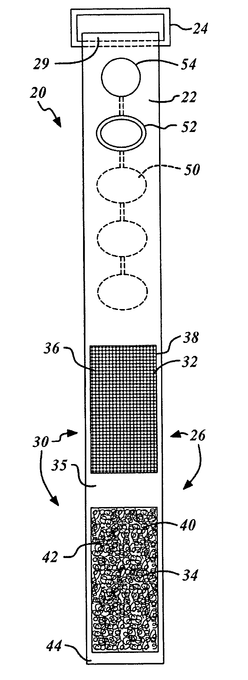
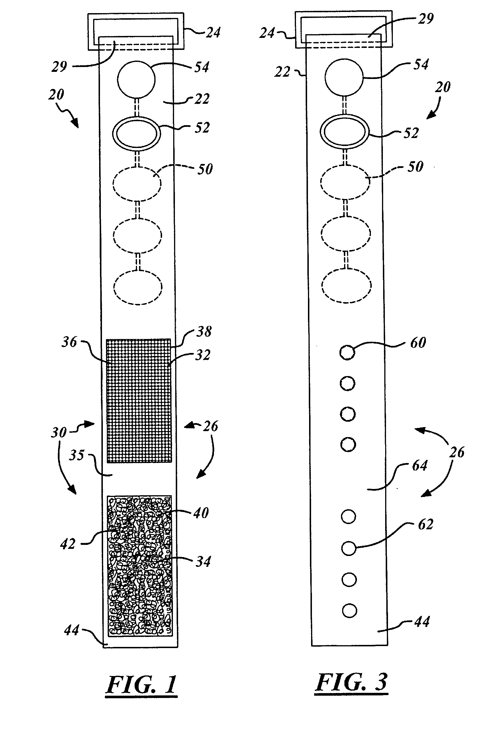
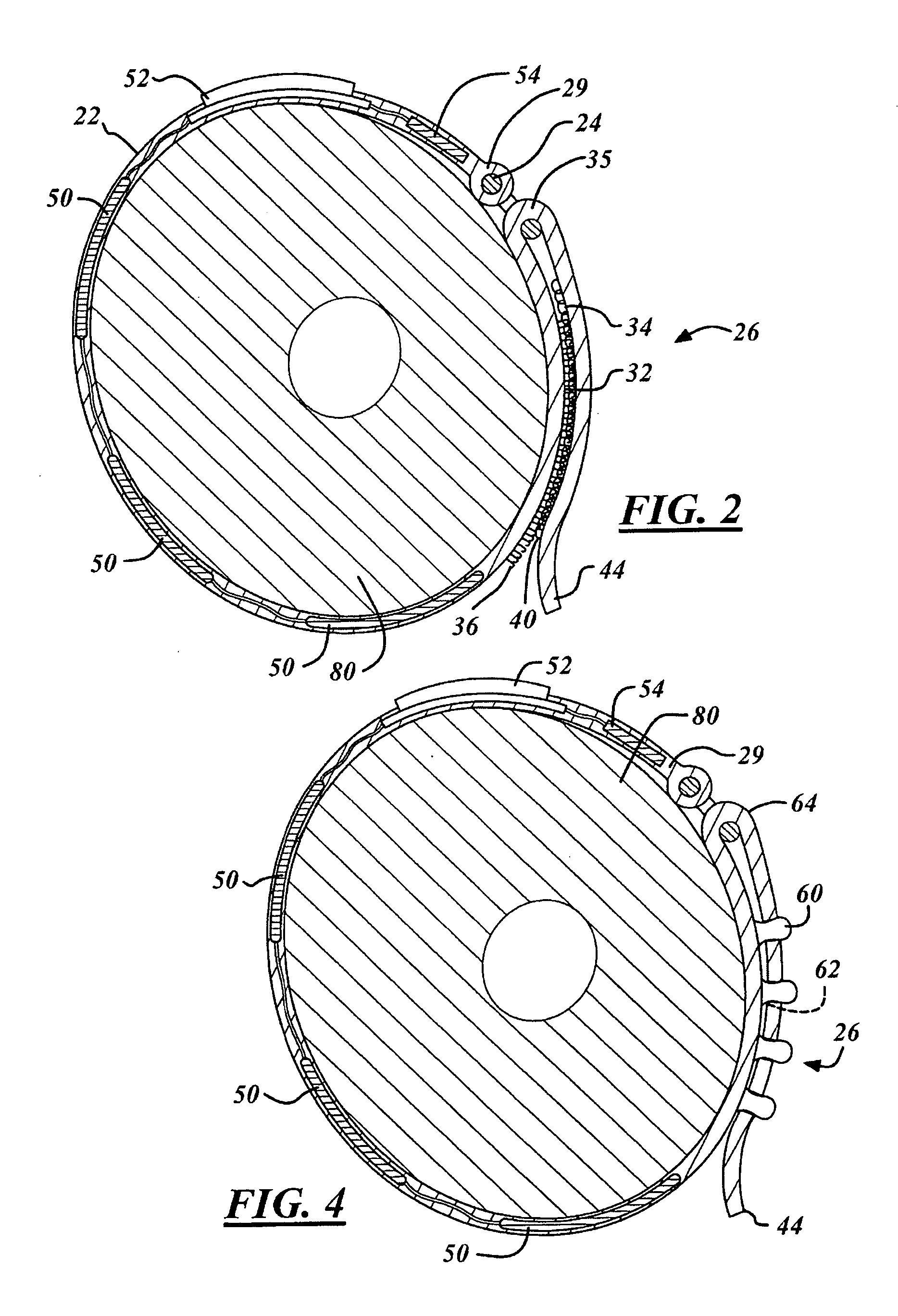
[0014] Referring now to FIGS. 1 and 3, two preferred versions of a vibrating tourniquet 20 is illustrated having a strap portion 22. The strap portion 22 includes a fastening loop 24 at one end and a fastening mechanism 26 closer to its other end.

[0015] The strap portion 22 is formed of a pliable, or otherwise flexible, material. Preferred materials used in the strap portion include natural materials such rubber or manufactured fabrics. The fastening loop 24 is formed of hard rubber, plastic or metal and is retained within a looped end portion 28 of the strap portion 22. Alternatively, the fastening loop 24 may be secured to the end portion 29 of the strap by an adhesive or other means well known to those of ordinary skill in the art.

[0016] Coupled to the strap portion 22 between the fastening mechanism 26 and the fastening loop 24 are one or more vibrations devices 50 electrically coupled to a controller mechanism 52. The vibration devices 50 and controller mechanism 52. The cont...


PUM


Abstract

A vibrating tourniquet is disclosed in which one or more vibrating devices are coupled within a pliable strap portion and are activated to interrupt nerve transmissions, and supply an alternative stimulus, that decreases the sensation of pain as the needle or IV are introduced through the skin and into a vein. The vibration devices are electrically coupled to a controller mechanism and the controller mechanism may be turned on or off after the tourniquet is applied to the arm. In alternative versions, the frequency and amplitude of the vibration may be selectively increased or decreased cooperatively or separately by adjusting the controller mechanism as needed.

Description

TECHNICAL FIELD [0001] The present invention relates to a tourniquet, more particularly to a vibrating tourniquet. BACKGROUND OF THE INVENTION [0002] Tourniquets are used in medical emergencies to arrest life-threatening arterial or venous bleeding. A tourniquet is applied around an arm or leg, or other body extremity, to constrict the blood vessels between the patient's heart and the bleeding wound. Tourniquets must be used with care and knowledge, as stopping the flow of blood to the wound also stops the flow of blood to the entire extremity below the tourniquet; prolonged blood deprivation from improperly extended or regulated tourniquet use can lead to tissue death in the affected limb. [0003] Besides the first-aid application for stopping the bleeding, a tourniquet can also be used be used for intravenous injection (“IV” or angiocatheter) or blood drawing, in which the tourniquet is applied to a limb. The purpose of the tourniquet is to engorge the veins distal to the tournique...

Claims


Application Information

Patent Timeline
Patent Type & Authority Applications(United States)
IPC IPC(8): A61B17/00
CPCA61B17/1322
Inventor PERRY, ERIC S.
Owner PERRY ERIC S
Why Eureka
Try Eureka