

Reduced-Size Flat Drop Cable
a flat drop cable, reduced technology, applied in the field of optical fibers, can solve the problems of reducing the diameter of the mode field, affecting and the inability to install conduits suitable for traditional cable designs, etc., to achieve the effect of improving the protection against stress-induced microbending
- Summary
- Abstract
- Description
- Claims
- Application Information
AI Technical Summary
Benefits of technology
Problems solved by technology
Method used
Image

Examples
example 1
Comparison of Mechanical Properties
[0064]FIGS. 3 and 4, respectively, depict dynamic mechanical properties of a typical commercial primary coating (i.e., the conventional primary coating) and an exemplary primary coating used in making the optical fibers according to the present invention. The conventional primary coating was a UV-curable urethane acrylate provided by DSM Desotech (Elgin, Ill.) under the trade name DeSolite® DP 1007. The exemplary primary coating according to the present invention (i.e., employed to form optical fibers of the present invention) was a UV-curable urethane acrylate provided by DSM Desotech (Elgin, Ill.) under the trade name DeSolite® DP 1011.
[0065]The data for the conventional primary coating were obtained on a Dynamic Mechanical Analyzer (DMA) at an oscillatory stress rate of 1 Hz. In doing so, the strain was maintained within the linear region of stress-strain behavior. The sample of conventional primary coating was cured on polyester to form a stand...
example 2
Comparison of Microbending Sensitivity
[0073]The first test method employed was a basket-weave, temperature cycling procedure known by those having ordinary skill in the art. According to this test procedure, optical fiber was wound at about 490 mN (i.e., a tension of 50 gf on a 300-mm diameter quartz cylinder with a 9-mm “lay”). Fifty layers were wound on the quartz drum to create numerous fiber-to-fiber crossovers. The testing procedure for Example 2 was an adaptation of IEC TR62221, Method D, which, as noted, is incorporated by reference in its entirety.
[0074]Those having ordinary skill in the art will appreciate that, at room temperature, such fiber crossovers can sometimes cause added loss (i.e., if the optical fiber is very sensitive) but that typically little or no added loss is observed. Consequently, the drum (with wound fiber) was temperature cycled twice from about room temperature through (i) −40° C., (ii) −60° C., (iii) +70° C., and (iv) +23° C. (i.e., near room temperat...
example 3
Comparison of Microbending Sensitivity
[0078]The second test method employed more aggressive environments (i.e., conditions) in order to evaluate the respective microbend sensitivities of (i) an optical fiber possessing a typical commercial primary coating (i.e., the conventional primary coating) and (ii) an optical fiber possessing an exemplary primary coating according to the present invention.
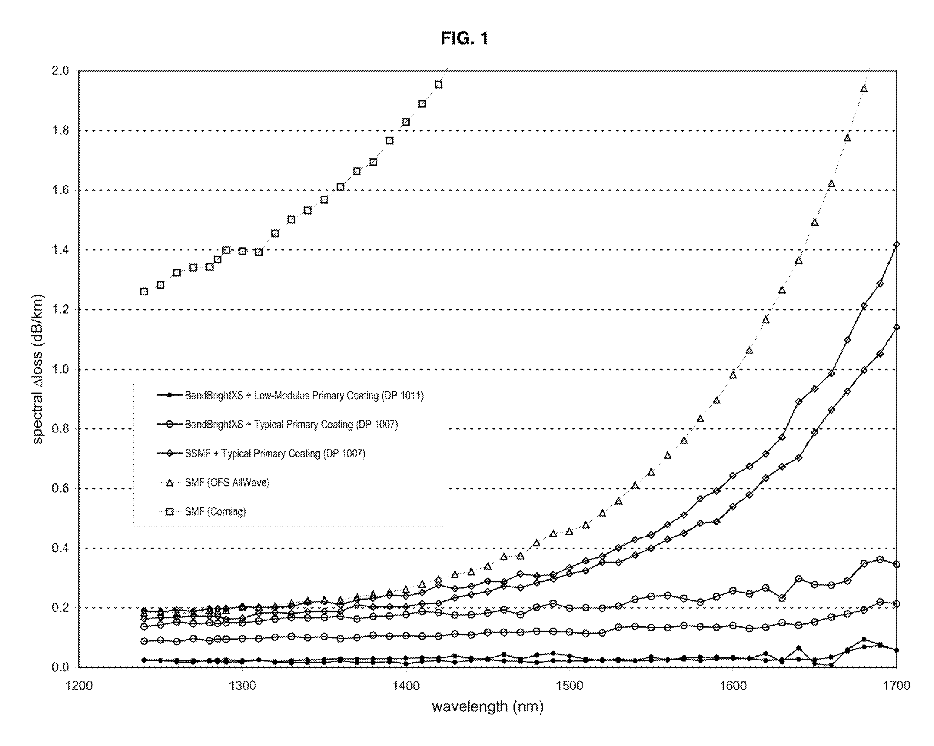
[0079]In particular, the second method modified the IEC fixed-diameter sandpaper drum test (i.e., IEC TR62221, Method B), which, as noted, is incorporated by reference in its entirety, to provide a microbending stress situation sufficiently harsh to affect single-mode fibers even at room temperature (i.e., a rougher drum surface than that used to measure the data depicted in FIG. 1). To do this, a 300-mm diameter quartz drum was wrapped with adhesive-backed, 220-grit sandpaper (i.e., approximately equivalent to 66-micron-grade sandpaper) to create a rough surface.
[0080]In an initial test cond...
PUM
| Property | Measurement | Unit |
|---|---|---|
| Temperature | aaaaa | aaaaa |
| Pressure | aaaaa | aaaaa |
| Pressure | aaaaa | aaaaa |
Abstract
Description
Claims
Application Information