Retractable catheter

a catheter and retraction technology, applied in the field of retraction catheters, can solve the problems of reducing the number of components, and reducing the cost of material and labor

Active Publication Date: 2010-06-10
CR BARD INC
View PDF29 Cites 15 Cited by
  • Summary
  • Abstract
  • Description
  • Claims
  • Application Information

AI Technical Summary

Benefits of technology

[0009]Since the pull element is embedded in the relatively flexible material, even large friction forces between the tubular sheath and the pull element can be overcome, without the need to add further connecting or reinforcing elements, which can provide the catheter with a bigger gap between the inner catheter and the outer sheath for the same overall outside diameter. Additionally, this reduces the number of components in the assembly, so that material and labour costs can be decreased, and the assembling process is facilitated.
[0010]Preferably, at least part of the end portion of the pull element is a plate member. More preferably, the end portion is encased within the relatively flexible material between radially inner and outer surfaces of the tubular sheath. In one preferred embodiment, at least part of the end portion is the flattened end of a wire. These arrangements can increase the contact surface area between the flexible material of the sheath and the end portion, improving the bond strength therebetween.
[0011]In preferred embodiments, the end portion comprises a stepped and / or tapered portion, in its width and / or thickness directions, along its length. The stepped and / or tapered portion may increase the width and / or the thickness of the end portion in a direction from the proximal end to the distal end of the end portion. The end portion may comprise protrusions, at the distal and / or proximal ends, in the width and / or thickness directions. These step portions or tapered portion again increase the friction and the force transmission between the end portion and the outer sheath. In particular, if these portions increase the width and / or thickness in a direction from the proximal end to the distal end of the end portion, it can be firmly anchored in the relatively flexible sheath material.
[0013]In preferred embodiments, the end portion has a rougher surface than a more proximal portion of the pull element, preferably an Ra surface roughness of between 10 μm and 25 μm. Similarly, or to provide the roughness, the end portion may comprise, at least on a surface which faces radially inwardly or outwardly in the tubular sheath, protrusions and / or micro-protrusions. In the same way, the end portion may comprise, at least on a surface which faces radially inwardly or outwardly in the tubular sheath, recesses and / or micro-recesses. Instead of or additionally thereto, the end portion may be perforated with holes and / or micro-holes. These surface treatments can increase the bond contact area between the pull element and sheath, and so improve force transmission therebetween and increase the bond strength.

Problems solved by technology

Since a greater force has to be applied, the possibility arises that the inner shaft may deflect or move under compression, as tension is applied to the pull wire.
Larger forces will also tend to break the connection between the pull wire and sheath.
Another disadvantage of such an arrangement is that the diameter of the outer sheath has to be at least large enough, for the inner shaft, the stent and the inner ring to be accommodated in the sheath.
Furthermore, the outer rings increase the thickness of the device as well, at least if one is clamped directly on the inner ring, and may distort the outside surface of the outer sheath.
Since an application of such an implant catheter delivery system is for delivery of stents by advancing the catheter system into a bodily lumen, a thicker diameter reduces the range of possible treatment opportunities, especially in the narrow confines of a patient's vasculature, or may give rise to a risk of injury as the catheter system is advanced.

Method used


Image

  • Retractable catheter
  • Retractable catheter
  • Retractable catheter

Examples


Embodiment Construction

[0026]In the following, the expressions “distal”, meaning away from the operator's side, and “proximal”, meaning towards the operator's side, are used, and define also respective directions which are substantially along the longitudinal axis of the delivery catheter.

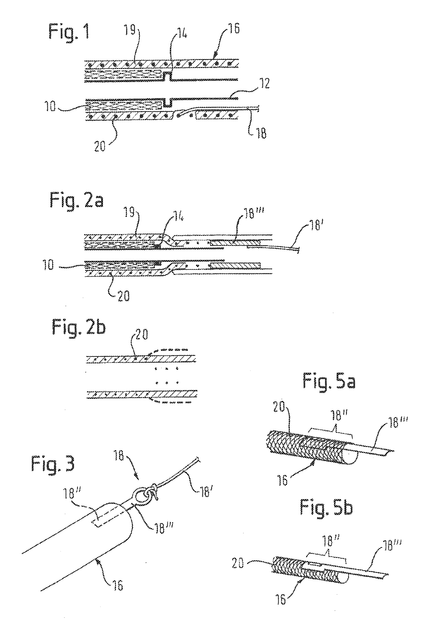
[0027]Referring to FIG. 1, a self-expanding implant 10, known as a stent, is placed around a shaft tube 12 and abuts on an abutment member 14 that can be formed integrally with the shaft tube 12 or can be a separate member, as for example a ring clamped or otherwise fixed on the shaft tube. The shaft tube 12 can be strengthened by a supporting member, such as a steel spring wound tightly to resist compression but to allow off-axis flexibility, in particular if the implant is very long.

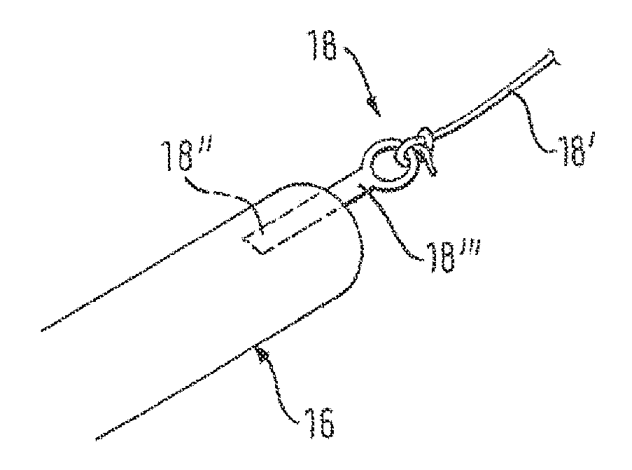
[0028]Around this arrangement is disposed an outer catheter sheath 16 that covers the distal end portion of the shaft tube 12 and the implant 10. The outer catheter sheath 16 extends longitudinally from a distal end in a proximal direction....


PUM

PropertyMeasurementUnit
Ra surface roughnessaaaaaaaaaa
lengthaaaaaaaaaa
lengthaaaaaaaaaa

Abstract

A retractable catheter for use in an implant delivery system, the catheter including an elongate tubular sheath made of a relatively flexible material, and a pull element for transmitting a pull force to the sheath to retract it longitudinally. The pull element includes an end portion disposed in the relatively flexible material, at least the thickness of the end portion being substantially less than its length.

Description

PRIORITY[0001]This application claims the benefit of priority to U.S. Provisional Patent Application No. 61 / 119,668, filed Dec. 3, 2008, and to U.K. Patent Application No. 0822106.1, filed Dec. 3, 2008, each of which is incorporated by reference into this application as if fully set forth herein.FIELD OF THE INVENTION[0002]This invention relates to a retractable catheter preferably for use as an outer sheath in an implant catheter delivery system, and to a method of manufacturing a retractable catheter. Such a catheter is preferably sized to be inserted in a bodily lumen. Such a retractable catheter includes a pull element connected at its distal end to an elongate tubular sheath.BACKGROUND ART[0003]Conventional implant catheter delivery systems comprise an inner shaft that extends from a proximal end to a distal end of the system and carries on its distal end a self expanding implant. A longitudinal tubular sheath lies radially outside the implant to retain the implant in the cathe...

Claims


Application Information

Patent Timeline
Patent Type & Authority Applications(United States)
IPC IPC(8): A61M25/00B23P17/04A61F2/95A61F2/966
CPCA61F2/95Y10T29/49826A61F2/966A61F2250/0018
Inventor TOLLNER, THOMASWUBBELING, MARTINDORN, JURGEN
Owner CR BARD INC
Why Eureka
Try Eureka