Solar cell module

Inactive Publication Date: 2010-06-17
SANYO ELECTRIC CO LTD
View PDF4 Cites 6 Cited by
  • Summary
  • Abstract
  • Description
  • Claims
  • Application Information

AI Technical Summary

Benefits of technology

[0007]In the solar cell module described above, the extracting wire member is not in direct contact with the bonding layer. This makes it possible to reduce stress which the extracting wire member undergoes from the bonding la

Problems solved by technology

The repetition of application of such stress on the extracting wire member accumulates damage in a connection portion between the extracting wire member and t

Method used


Image

  • Solar cell module
  • Solar cell module
  • Solar cell module

Examples


Example

First Embodiment

Structure of Solar Cell Module

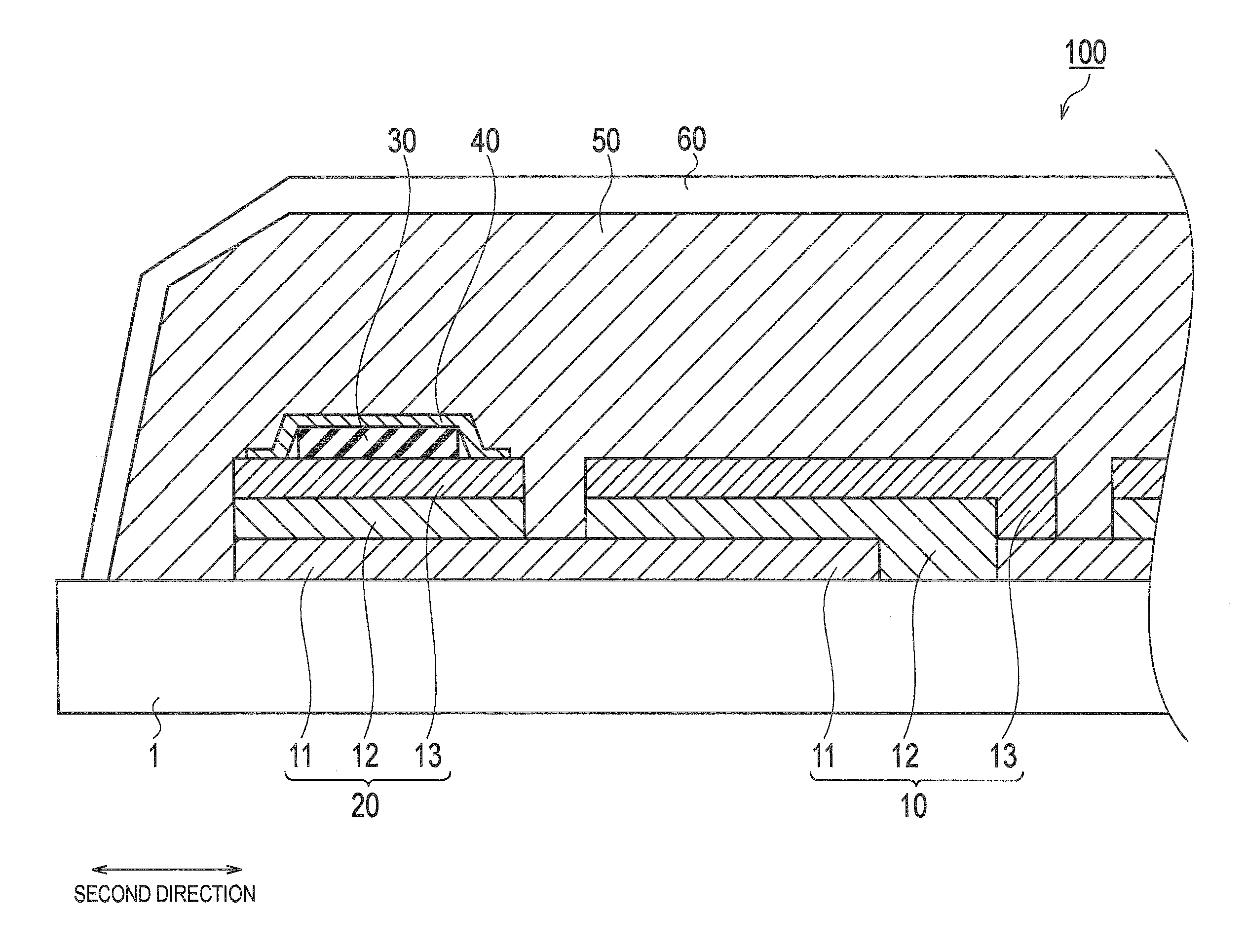
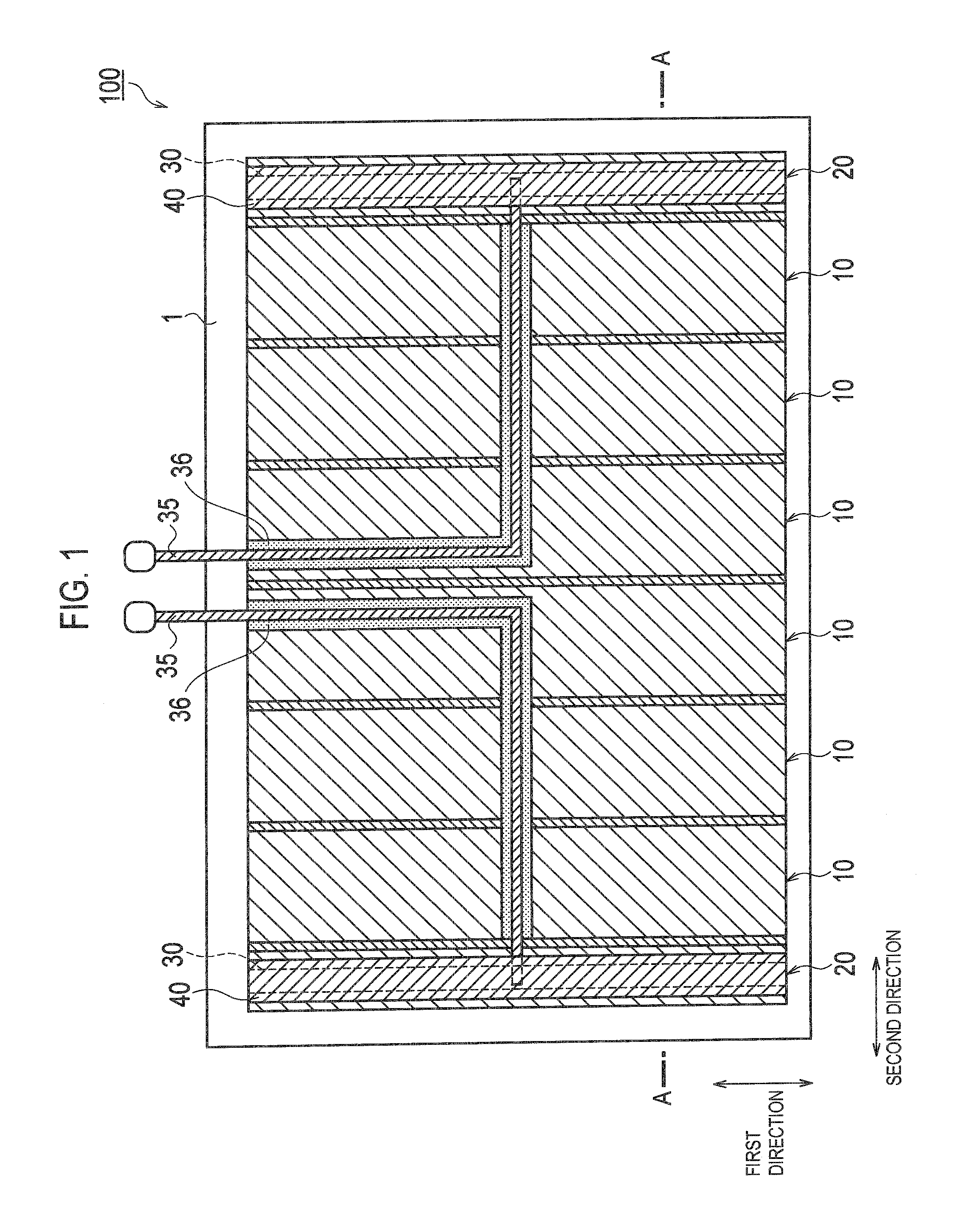
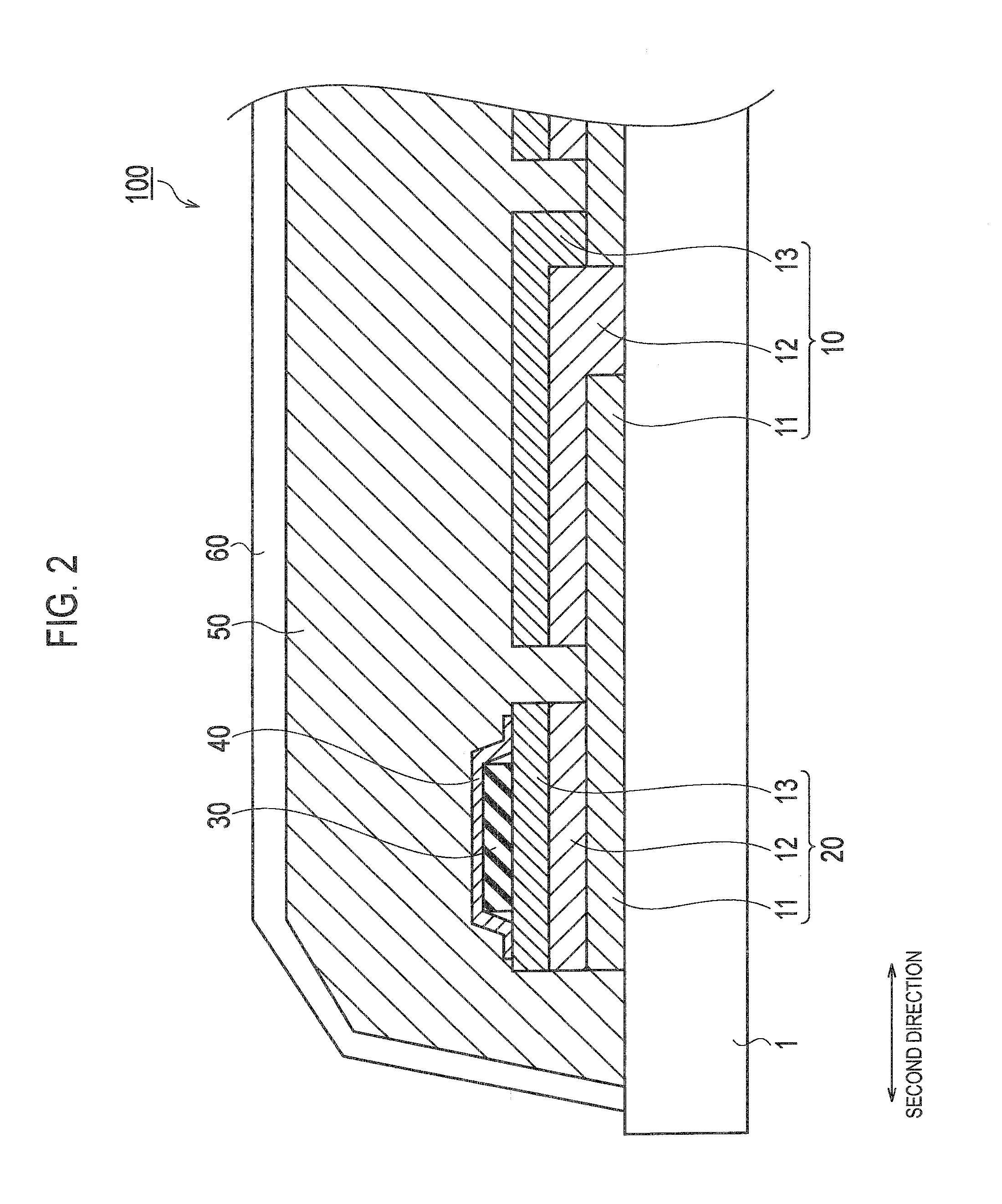
[0014]A structure of a solar cell module 100 according to an embodiment of the present invention will be described with reference to FIG. 1 and FIG. 2. FIG. 1 is a plan view showing the rear side of the solar cell module 100. FIG. 2 is an enlarged cross-sectional view taken along the line A-A of FIG. 1.

[0015]As shown in FIG. 1 and FIG. 2, the solar cell module 100 includes a substrate 1, multiple solar cells 10, an extracting electrode 20, an extracting wire member 30, an output wire member 35, an insulating film 36, a covering member 40, a bonding layer 50 and a protection member 60. Note that, in FIG. 1, the bonding layer 50 and the protection member 60 are omitted.

[0016]The substrate 1 is a single substrate for forming the multiple solar cells 10 and the extracting electrode 20 thereon. Glass, plastic or the like having an insulation property can be used as the substrate 1.

[0017]Each of the multiple solar cells 10 is formed in a fi...

Example

Second Embodiment

[0039]Next, a second embodiment of the present invention will be described. The point where this embodiment is different from the above-described first embodiment is the structure of the covering member 40. Other points are the same as the above-described first embodiment, and thus the different point will be mainly described below.

[0040]A covering member 40 according to this embodiment covers the extracting electrode 20 and the extracting wire member 30. Accordingly, as shown in FIG. 3, the extracting electrode 20 and the extracting wire member 30 are not in direct contact with the bonding layer 50. In this manner, the extracting electrode 20 and the extracting wire member 30 are isolated from the bonding layer 50 by the covering member 40.

[0041]Here, the covering member 40 according to this embodiment is a strip-shaped member. A flexible material such as a PET film, and a non-flexible material such as ceramics may be used for the covering member 40. As shown in ...


PUM


Abstract

A solar cell module includes an extracting wire member 30 which is connected to the extracting electrode 20, a covering member 40 covering the extracting wire member 30 and a bonding layer 50 bonding these. The extracting wire member 30 is isolated from the bonding layer 50 by the covering member 40.

Description

TECHNICAL FIELD[0001]The present invention relates to a solar cell module including multiple solar cells which are electrically connected to each other in series on a single substrate.BACKGROUND ART[0002]There has been heretofore known a solar cell module including multiple solar cells which are electrically connected to each other in series on a single substrate (see JP-A 2007-35695, for example). Such a solar cell module includes an extracting electrode formed on the single substrate and used to extract electric charges generated by the multiple solar cells to the outside. An extracting wire member which collects electric charges from the extracting electrode is connected to the extracting electrode.[0003]The multiple solar cells, the extracting electrode and the extracting wire member are bonded by a bonding layer, and thus the extracting wire member is in direct contact with the bonding layer. In general, copper is used for a base material of the extracting wire member, whereas ...

Claims


Application Information

Patent Timeline
IPC IPC(8): H01L31/042
CPCH01L31/02008H01L31/048Y02E10/50H01L31/0481H01L31/042
Inventor YAGIURA, TOSHIO
Owner SANYO ELECTRIC CO LTD
Why Eureka
Try Eureka