Silicon core wire holder and polycrystalline silicon manufacturing method

Inactive Publication Date: 2014-01-30
SHIN ETSU CHEM IND CO LTD
View PDF3 Cites 4 Cited by
  • Summary
  • Abstract
  • Description
  • Claims
  • Application Information

AI Technical Summary

Benefits of technology

[0032]Using the silicon core wire holder of the present invention allows the silicon core wire to be fixed substantially symmetrically and uniformly from both ends of the core wire insert hole. For this reason, a thermal environment including thermal conductivity and thermal radiation becomes uniform from the initial stage of the deposition reaction. Accordingly, the shape of the deposited polycrystalline silicon becomes symmetrical with respect to the axis.
[0033]Further, electric discharge, which has tended to occur when the silicon core wire holder having th

Problems solved by technology

Conventionally, a problem has been recognized that falling of the polycrystalline silicon rod occurs during the process or after the process of vapor phase growth of such polycrystalline silicon.
However, supplying the source gas at a high flow rate or at a high concentration at the initial stage of growth is likely to cause the silicon core wire to fall.
The falling of the silicon core wire tends to occur at a stage where joint strength between the silicon core wire and the core wire holder is insufficient.
This is considered to be attributable to the fact that, at the initial stage of the growth of polycrystalline silicon, the polycrystalline silicon grows non-uniformly on the silicon core wire near a silicon core wire holding part (joint part) of the core wire holder.
In addition, an inner area of the hole part 21 which is not in close contact with the silicon core wire 5 is susceptible to electric discharge, which is likely to cause damage to the silicon core wire 5.
Thus, the same problem as mentioned above occurs.
Thus, especially at the initial stage of deposition reaction, compared with the straight body part, the diameter of polycrystalline silicon is pronouncedly thin near the silicon core wire holding part

Method used


Image

  • Silicon core wire holder and polycrystalline silicon manufacturing method
  • Silicon core wire holder and polycrystalline silicon manufacturing method
  • Silicon core wire holder and polycrystalline silicon manufacturing method

Examples


Example

Example 1

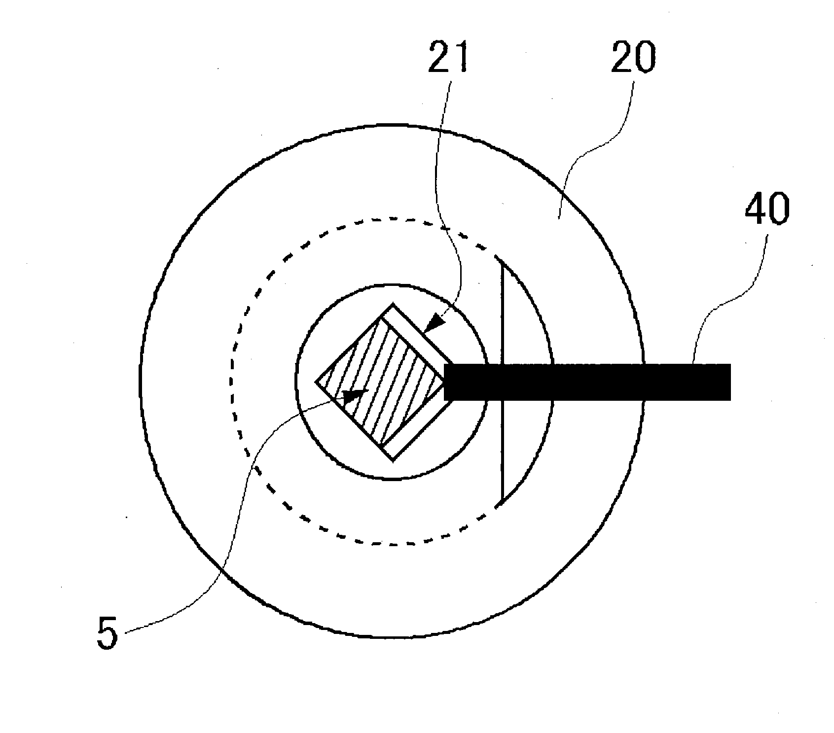
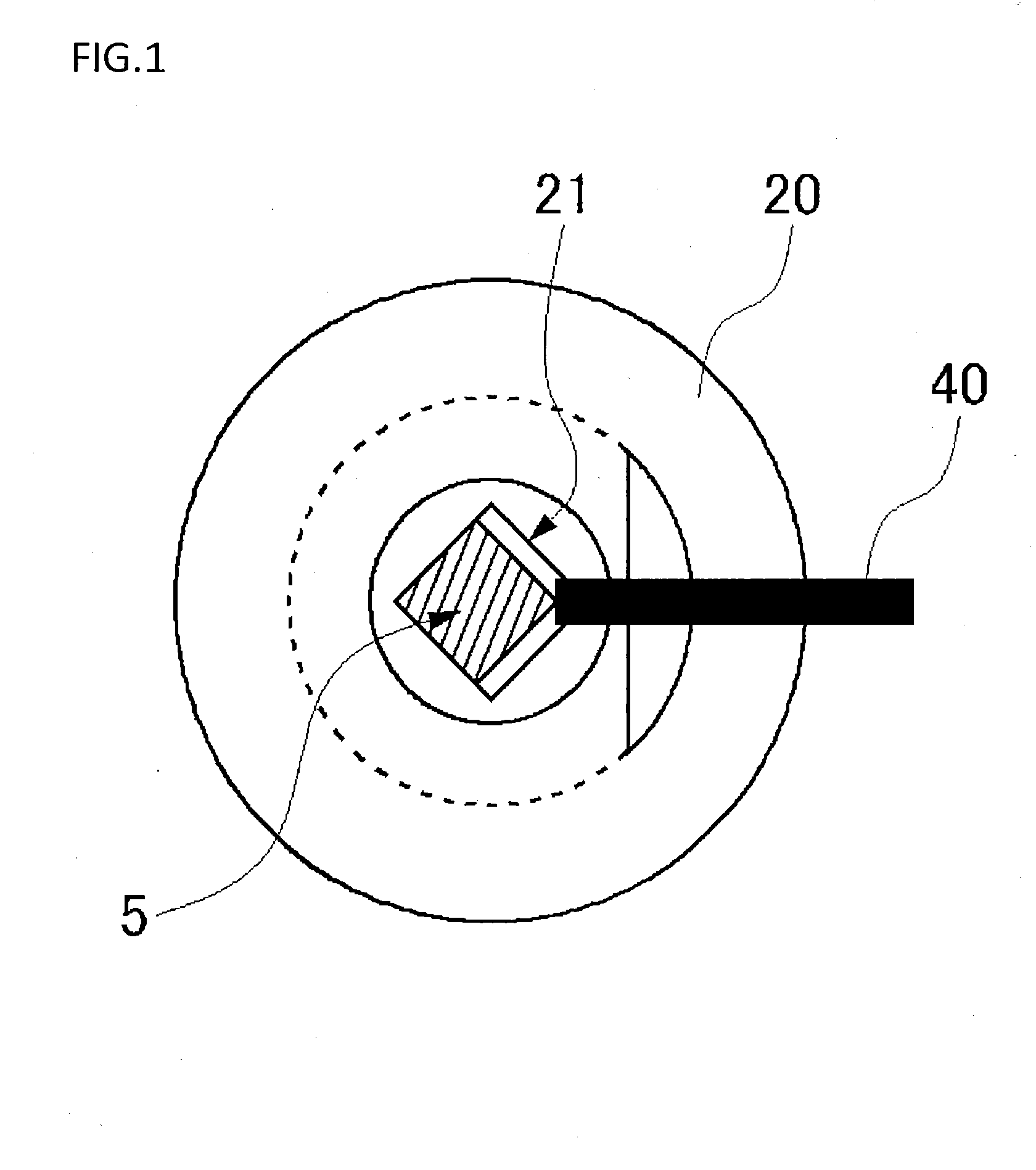
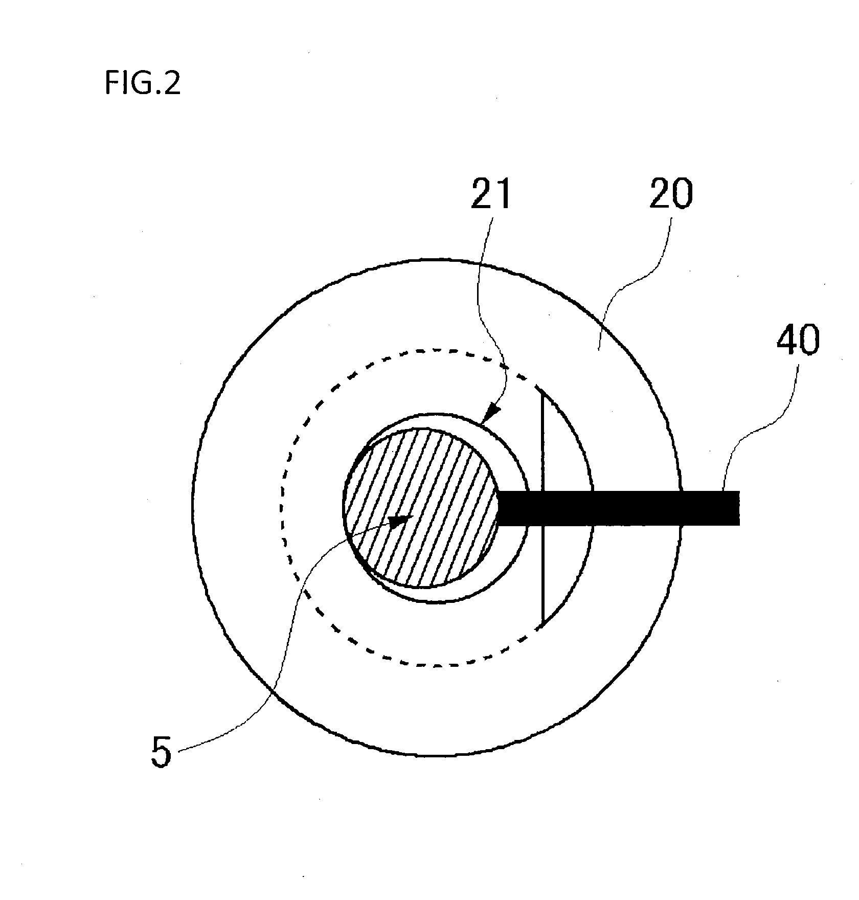
[0110]The core wire holder 20 made of graphite with the upper end side formed into a truncated cone shape was used. The insert hole 30 for a 4 mm screw is formed, in the slope surface of the truncated cone shape at a position 10 mm away from the opening part 22 of the core wire insert hole 21, so as to extend toward the core wire insert hole 21, and the slit 60 is provided in a longitudinal direction in the opening part 22.

[0111]In addition, the silicon core wire 5 was used, in which the through-hole 32 is opened such that, when the silicon core wire 5 is inserted to the bottom of the core wire insert hole 21, the bolt 31a, which is the common fixing shaft, passes through the insert hole 30 of the core wire holder and the through-hole 32 of the silicon core wire 5.

[0112]Further, the conductive sheet 61 having a specific resistance equivalent to that of the core wire holder 20 is inserted between contact surfaces of an inner surface of the core wire insert hole 21 and the si...

Example

Example 2

[0115]The core wire holder 20 made of graphite which is the same type as in Example 1 was used. Trichlorosilane gas along with hydrogen gas was supplied as a source gas while the silicon core wire 5 held in the core wire holder 20 was being heated to 1050° C. In a 12-hour period of growth rate inhibition after the start of vapor phase growth, a first end side of the core wire holder 20 was covered uniformly by deposition of the polycrystalline silicon 6. At that time, the diameter of the polycrystalline silicon 6 was 13 mm and the current value was 195 A. From this point, the supply gas amount started to be increased, and then, the current value was increased with the growth in the diameter of the polycrystalline silicon rod. In 62 hours, polycrystalline silicon having a diameter of 119 mm was obtained.

Example

Comparative Example 1

[0116]The core wire holder 20 made of graphite was used, which is formed of the same material as in Example 1 and is the core wire holder 20 of the conventional type having the structure shown in FIG. 1. Trichlorosilane gas along with hydrogen gas was supplied as a source gas while the silicon core wire 5 held in the core wire holder 20 was being heated to 1055° C. In a 16-hour period of growth rate inhibition after the start of vapor phase growth, the diameter of polycrystalline silicon 6 was 18 mm and the current value was 240 A. As with Examples 1 and 2, the current value was increased after the supply gas amount was increased. However, already at this point, the shape of the deposited polycrystalline silicon 6 on the upper end side of the core wire holder 20 was non-uniform as shown in FIG. 10. Although after that the vapor phase growth was continued at a current value of 514 A, the polycrystalline silicon rod fell at a point when the diameter of the polycry...


PUM


Abstract

A core wire holder 20 is formed with a core wire insert hole 21 having an opening part 22 on an upper surface of a main body and extending toward a lower surface side, and a silicon core wire 5 is inserted into the core wire insert hole 21. In addition, a slit-like gap part 60 extending along a virtual plane P including a central axis C of the core wire insert hole 21 is formed, and the slit-like gap part 60 is a gap part extending from the core wire insert hole 21 to reach an outer surface of the main body of the holder 20. The silicon core wire 5 inserted in the core wire insert hole 21 is fixed by fastening an upper part of the main body of the holder 20 from sides with, for example, a bolt/nut type fixing member 31.

Description

TECHNICAL FIELD[0001]The present invention relates to a core wire holder used for manufacturing polycrystalline silicon and a polycrystalline silicon manufacturing method using the core wire holder.BACKGROUND ART[0002]A Siemens method is known as a method for manufacturing polycrystalline silicon which is used as a raw material of single crystalline silicon for manufacturing semiconductors or of silicon for manufacturing solar cells. The Siemens method is a method in which a source gas including chlorosilane is brought into contact with a heated silicon core wire, and thereby polycrystalline silicon is vapor-grown on a surface of the silicon core wire through a CVD (Chemical Vapor Deposition) process.[0003]When polycrystalline silicon is to be vapor-grown by the Siemens method, two silicon core wires held in a vertical direction and one silicon core wire held in a horizontal direction are assembled into an inverted U-shape in a reactor of a vapor deposition device. Then, both ends o...

Claims


Application Information

Patent Timeline
IPC IPC(8): C01B33/035
CPCC01B33/035
Inventor NETSU, SHIGEYOSHIKUROSAWA, YASUSHI
Owner SHIN ETSU CHEM IND CO LTD
Why Eureka
Try Eureka