Variable Angle Connection Assembly

Active Publication Date: 2010-06-24
GLOBUS MEDICAL INC
View PDF13 Cites 27 Cited by
  • Summary
  • Abstract
  • Description
  • Claims
  • Application Information

AI Technical Summary

Benefits of technology

[0005]In a preferred embodiment, the present invention provides a connection assembly that can be used to securely connect a spinal implant to a bone anchor. In particular, the present invention preferably provides a variable angle connection assembly that is able to securely connect the spinal implant to the anchors eve

Problems solved by technology

As a result, it can be difficult to obtain a secure con

Method used


Image

  • Variable Angle Connection Assembly
  • Variable Angle Connection Assembly
  • Variable Angle Connection Assembly

Examples


Embodiment Construction

[0016]The following description of the preferred embodiment(s) is merely exemplary in nature and is in no way intended to limit the invention, its application, or uses.

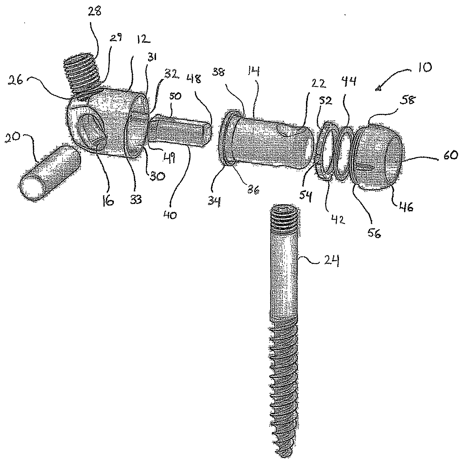
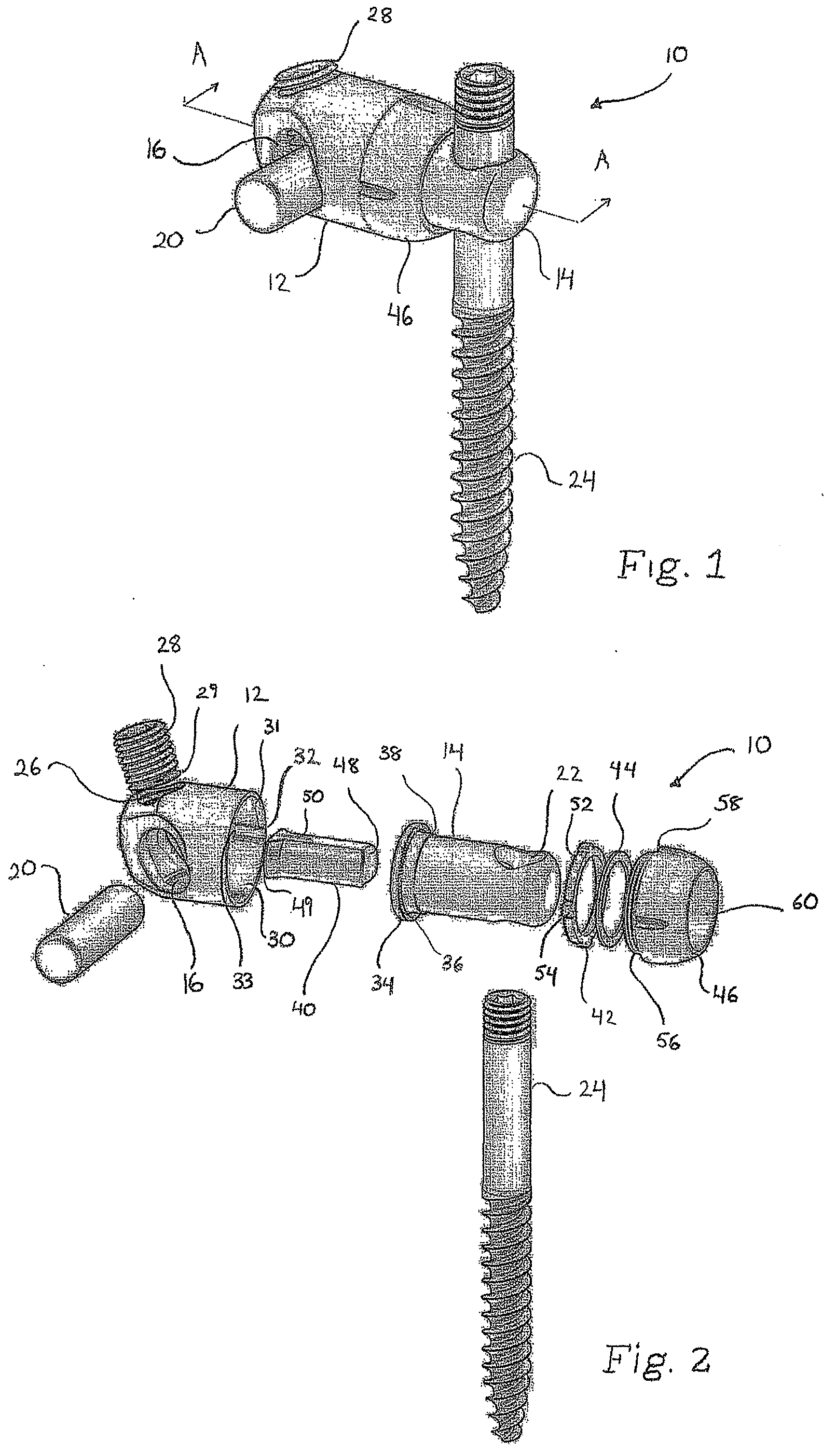
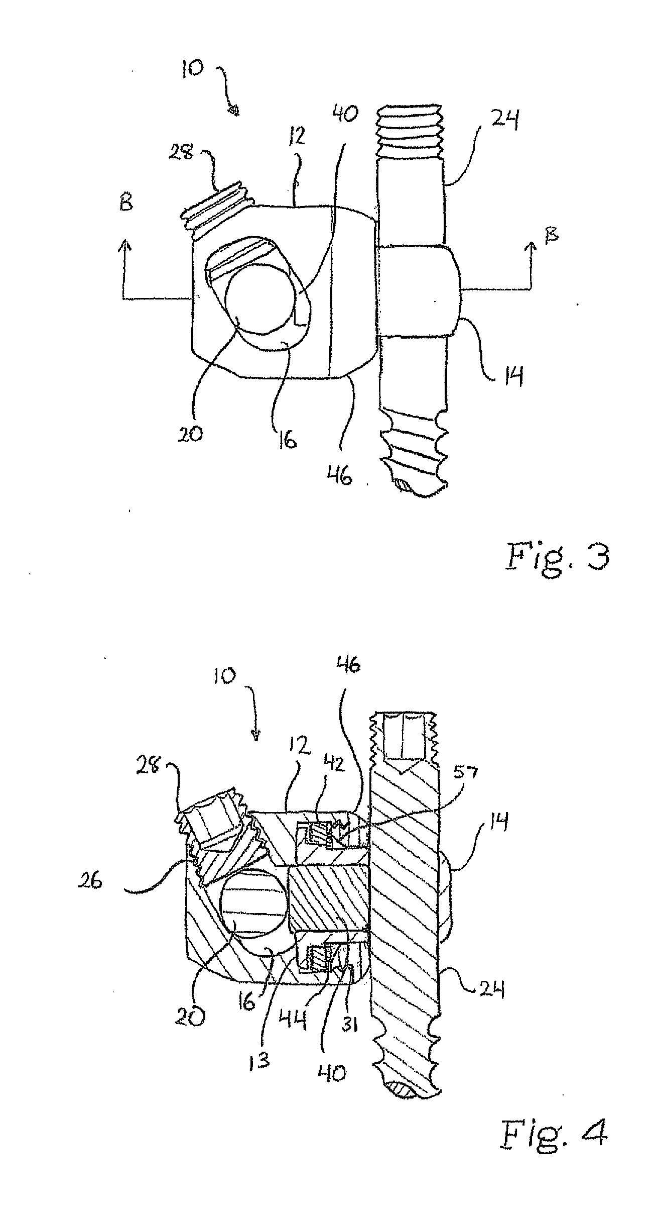
[0017]With reference to FIGS. 1-4, a preferred embodiment of a connection assembly 10 is illustrated. The connection assembly 10 preferably includes a housing member 12 and a receiving member 14. The housing member 12 includes an elongated aperture 16 at a first end for receiving at least a portion of a spinal implant 20, such as a spinal rod, and the receiving member 14 includes an aperture 22 at a first end for receiving at least a portion of an anchor 24, such as a bone screw. One of ordinary skill in the art would recognize that although only a bone screw is shown, the aperture 22 of the receiving member 14 is capable of receiving any number of anchors including, but not limited to, other orthopedic screws, hooks, bolts, or other similar bone anchoring devices. The housing member 12 and the receiving member 14 are...


PUM


Abstract

In a preferred embodiment, the present invention provides a connection assembly that can be used to securely connect a spinal implant to a bone anchor. In particular, the present invention preferably provides a variable angle connection assembly that is able to securely connect the spinal implant to the anchors even when there is a variance in the angle and position of the anchors with respect to the spinal implant. Furthermore, in a preferred embodiment, the present invention provides a connection assembly that will not inadvertently lock the components of the connection assembly preventing the relative movement of the components.

Description

FIELD OF THE INVENTION[0001]The present invention relates generally to a connection assembly, and more particularly, to a variable angle spinal implant connection assembly.BACKGROUND OF THE INVENTION[0002]Spinal deformities, spinal injuries, and other spinal conditions may be treated with the use of spinal implants. Spinal implants are designed to support the spine and properly position the components of the spine. One such spinal implant includes an elongated rod and a plurality of bone anchors. The elongated rod is positioned to extend along one of more of the components of the spine and the bone anchors are attached to the spinal components at one end and secured to the elongated rod at the other end.[0003]However, due to the anatomical structure of the patient, the spinal condition being treated, and, in some cases, surgeon preference, the bone anchors may be required to be positioned at various angles and distances from the elongated rod. As a result, it can be difficult to obt...

Claims


Application Information

Patent Timeline
IPC IPC(8): A61B17/70A61B17/04
CPCA61B17/7037A61B17/7041A61B17/704A61B17/7038A61B17/7002
Inventor GLERUM, CHADHARPER, MICHAEL
Owner GLOBUS MEDICAL INC
Why Eureka
Try Eureka