Three-Dimensional Flame Simulating Electric Fireplace

Inactive Publication Date: 2010-07-08
YIWU ANDONG ELECTRICAL APPLIANCES
View PDF14 Cites 2 Cited by
  • Summary
  • Abstract
  • Description
  • Claims
  • Application Information

AI Technical Summary

Benefits of technology

[0014]Therefore, the present invention has the features of rational construction and easy

Problems solved by technology

The two types of flame simulating assembly both can produce a visual image of flicker flames, but these assemblies which use projection to form an image on one imaging screen produce a

Method used


Image

  • Three-Dimensional Flame Simulating Electric Fireplace
  • Three-Dimensional Flame Simulating Electric Fireplace
  • Three-Dimensional Flame Simulating Electric Fireplace

Examples


Embodiment Construction

[0020]The present invention will be further described by the following preferred embodiment in conjunction with the drawings thereof.

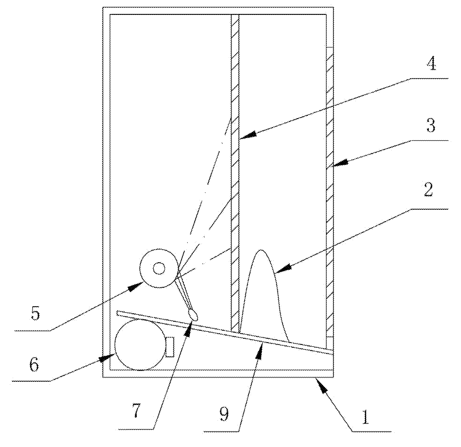
[0021]First referring to FIG. 1, the embodiment according to present invention is an electric fireplace having a 3D flame simulating assembly, which comprises a housing 1 of the electric fireplace, an imaging light source 7, light processing unit 5, simulated charcoal 2, translucent imaging screen 4 positioned against the back of the simulated charcoal 2, and the second imaging screen 3 in front of and approximately parallel to the imaging screen 4. The light emitted from the imaging light source is projected onto the imaging screen 4 to form a primary simulated flame image after passing through the light processing unit 5, and portion of which is further projected onto the second imaging screen 3 to form a secondary simulated flame image after passing through the image screen 4. If the distance between the imaging screen 4 and the second imaging scree...


PUM


Abstract

The present invention relates to an electric fireplace having a 3D flame simulating assembly, which comprises housing, an imaging light source, a light processing unit and a simulated charcoal disposed in front of the inner cavity of said housing. A translucent imaging screen is positioned against the back of the simulated charcoal and a second translucent imaging screen is positioned just in front of and parallel to the translucent imaging screen. The light emitted from the imaging light source is projected onto the imaging screen to form a primary simulated flame image after passing through the light processing unit, and portion of which is further projected onto the second imaging screen to form a secondary simulated flame image after passing through the image screen. If the distance between the imaging screen and the second imaging screen is kept to be enough, a visual effect of rising and leaping simulated flames with spatial depth is generated due to the different front to back positions of the flame images imaged on both screens.

Description

FIELD OF THE INVENTION[0001]The present invention relates to a heater, in particular, to an electric fireplace having a 3D flame simulating assembly.BACKGROUND OF THE INVENTION[0002]Electronic flame or simulated flame is usually used in electric fireplace having flame simulating assembly to produce vision and decorative effect. The traditional flame simulating assembly used in electric fireplace is generally divided into two types. For the first type, a set of silk strips, which are hung over the simulated fuel and positioned behind a translucent plastic screen and reflective glass, simulate the flicker flame via wobbling lights which is produced in the way that strips are blew by air and projected on to the reflective glass, as is disclosed in patent ZL200420025266.3 entitled ELECTRIC FIREPLACE HEATER. For the second type, a dynamic light source driven by an electric motor, a set of tree-branches-like simulated charcoal, a flame template wall, a transparent screen and a reflective ...

Claims


Application Information

Patent Timeline
IPC IPC(8): F24D13/00
CPCF24C7/004
Inventor ZHU, HONGFENG
Owner YIWU ANDONG ELECTRICAL APPLIANCES
Why Eureka
Try Eureka