Micro coaxial cable connector assembly with grounding mechanism

Inactive Publication Date: 2007-05-03
HON HAI PRECISION IND CO LTD
View PDF3 Cites 2 Cited by
  • Summary
  • Abstract
  • Description
  • Claims
  • Application Information

AI Technical Summary

Benefits of technology

[0006] Accordingly, an object of the present invention is to provide a cable con

Problems solved by technology

However, the shield is used to accept the grounding bar, so a volume of shield is big, and a figure of

Method used


Image

  • Micro coaxial cable connector assembly with grounding mechanism
  • Micro coaxial cable connector assembly with grounding mechanism
  • Micro coaxial cable connector assembly with grounding mechanism

Examples


Embodiment Construction

[0015] Reference will now be made to the drawing figures to describe the present invention in detail.

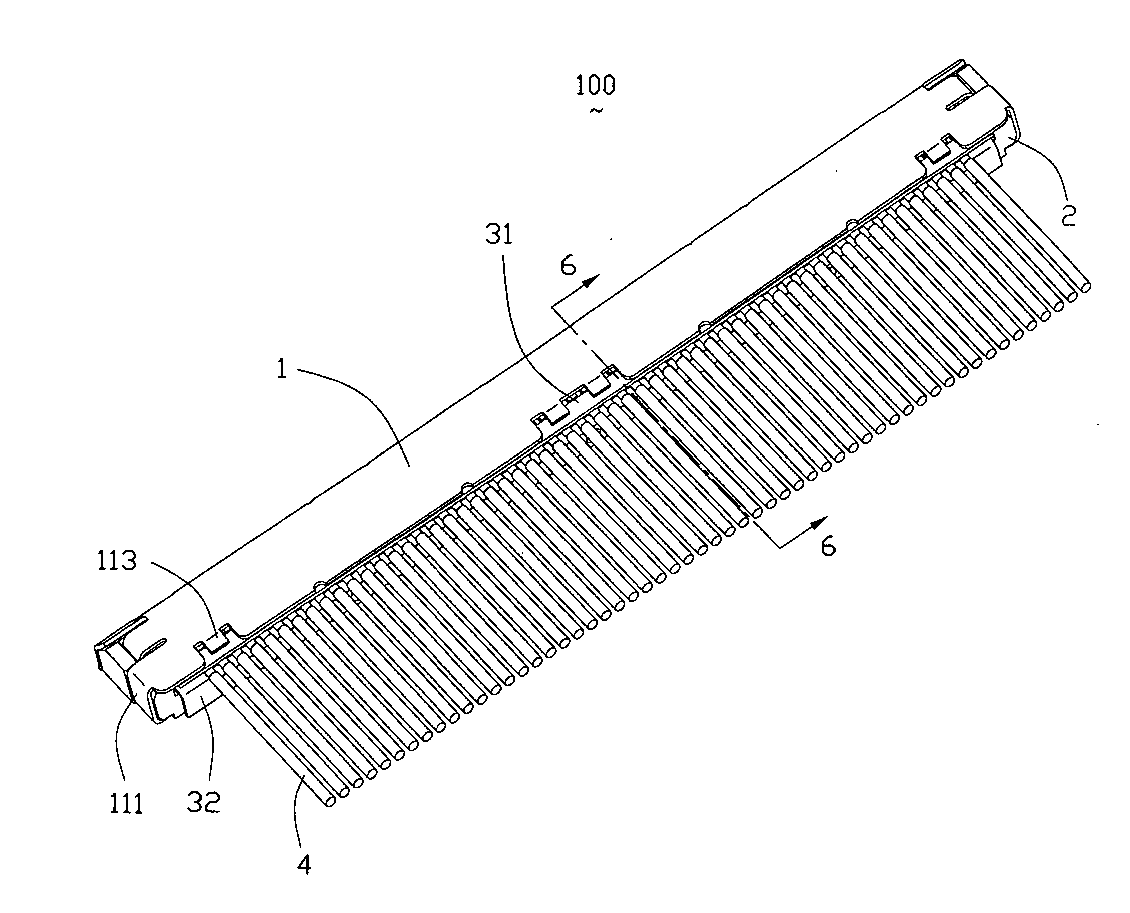
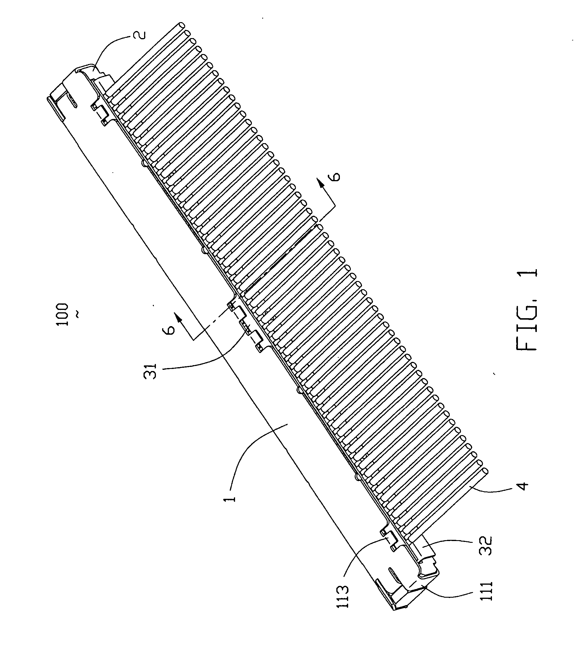
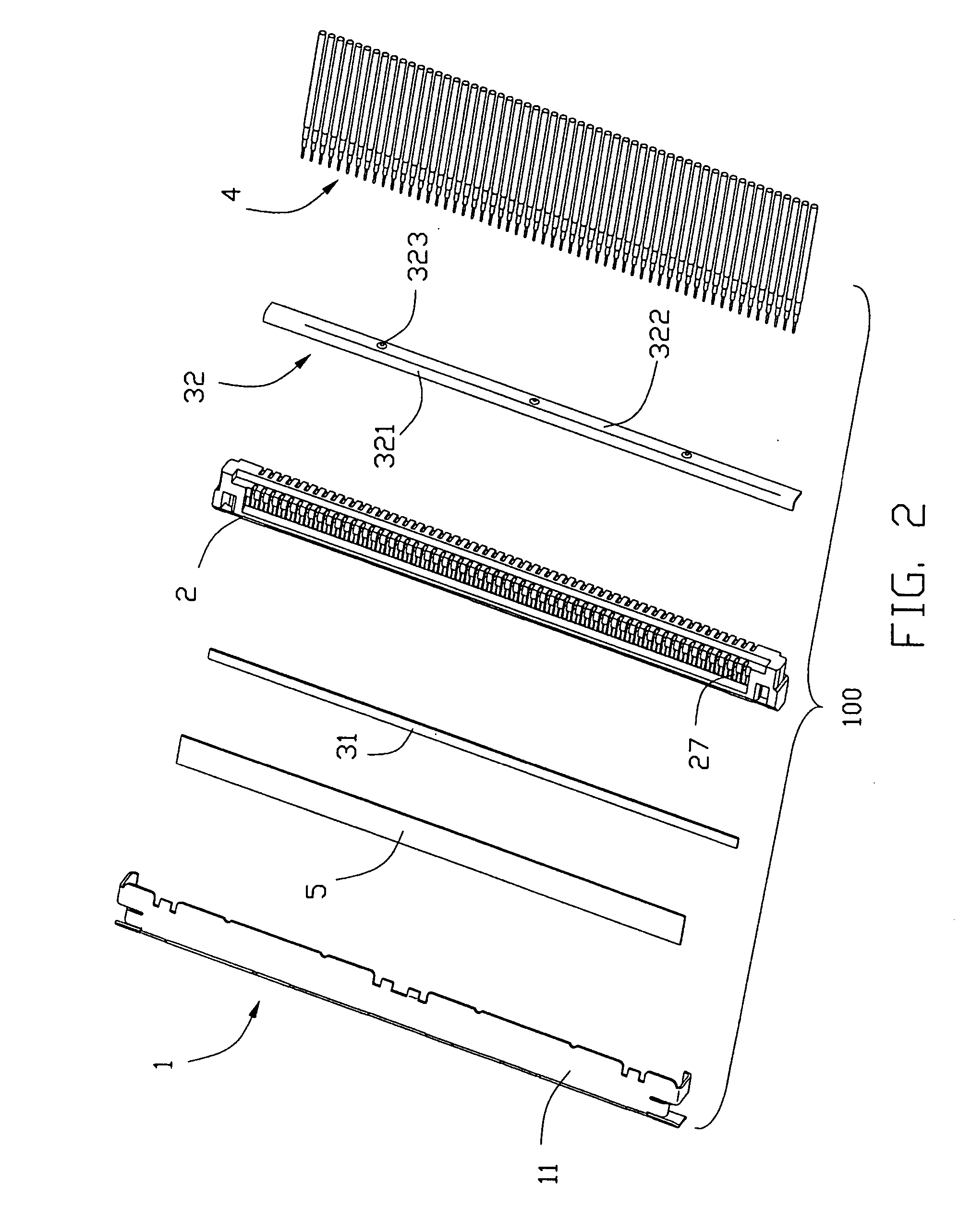
[0016] Referring to FIGS. 1-2, a cable connector assembly 100 of the present invention comprises a metal shield 1, an insulating housing 2 which is located in metal shield 1, a plurality of the contacts 27 which are located in the insulating housing 2, and a plurality of cables 4, a flat grounding bar 31 and a bended grounding bar 32 respectively located on the upside and downside of the cable 4, an insulating plate 5 located between the metal shield 1 and cable 4.

[0017] Referring to FIG. 2 and FIG. 6, viewed from center to outer, each cable 4 comprises a wire 44, an insulating layer 43, a metal braid 42 and an insulating shroud 41. The metal braid 42 connects with the bended grounding bar 32 for shielding the wire 44 and achieving a grounding performance.

[0018] Please referring to FIG. 3, the metal shield 1 comprises an up plate 11, a front plate 12 and an inclined plate 13. The ...


PUM


Abstract

A cable connector assembly (100) includes at least a cable (4); an insulating housing (2); a series of contacts (27) which are fixed in the insulating housing (2) to contact with the cable (4) electrically; a metal shield (1) engages with said insulating housing to shield the contacts (27) and cable (4); a bended grounding bar (32) is set between the insulating housing and cables, said bended grounding bar (32) formed an insert face (321) and a cover face (322), the insert face (321) electrically contact with the braid layer (42) of said cables and the cover face (322) covers on the insulating housing to screen it.

Description

BACKGROUND OF THE INVENTION [0001] 1. Field of the Invention [0002] The present invention generally relates to a cable connector assembly, and more particularly to a cable connector assembly with grounding bar. [0003] 1. Description of Related Art [0004] In the previous invention, the electric connector with grounding bar is popular to provide. Grounding bar is a metallic plate to connect with metal braid layer or grounding cable or shield so as to realize the grounding of the metal braid layer. However, the shield is used to accept the grounding bar, so a volume of shield is big, and a figure of the shield is complex, and this will increase the cost of manufacture and the difficulty of the design. [0005] Hence, an improved cable connector assembly is provided in the invention to address the problems mentioned above and meet the current trend. BRIEF SUMMARY OF THE INVENTION [0006] Accordingly, an object of the present invention is to provide a cable connector assembly, which can ach...

Claims


Application Information

Patent Timeline
IPC IPC(8): H01R13/648
CPCH01R13/6593
Inventor KUO, PETER
Owner HON HAI PRECISION IND CO LTD
Why Eureka
Try Eureka