Laminations for electric motors and a method of manufacturing the same

Active Publication Date: 2007-11-22
ERNESTO MALVESTITI
View PDF4 Cites 1 Cited by
  • Summary
  • Abstract
  • Description
  • Claims
  • Application Information

AI Technical Summary

Benefits of technology

[0034]The bosses of the lamination according to the invention can be easily made in a short time with the typical tolerances of a pressing process. The reduction in the section of a bo

Problems solved by technology

Regardless of the slot shape, when the pack is made up of a large number of laminations, any difference in the thickness that can be found between the different portions of the laminations can lead to inaccurate assembly.
The drawbacks of the traditional laminations are generally connected with the boss-boss coupling, particularly when the laminations are coupled in an offset manner.
The interference that is likely to occur between the ends of the coupled bosses can affect the evenness of the offset angle along the pack.
In other words, the bosses being coupled can interfere at the ends, thus actually changing the preset offset angle.
This problem is particularly importa

Method used


Image

  • Laminations for electric motors and a method of manufacturing the same
  • Laminations for electric motors and a method of manufacturing the same

Examples


Embodiment Construction

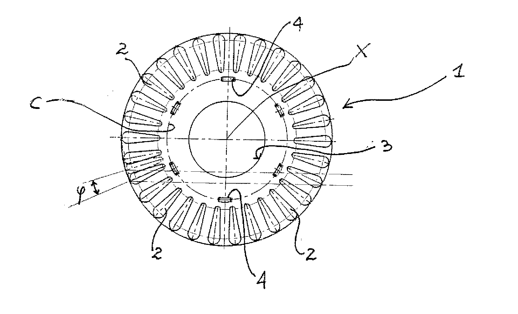
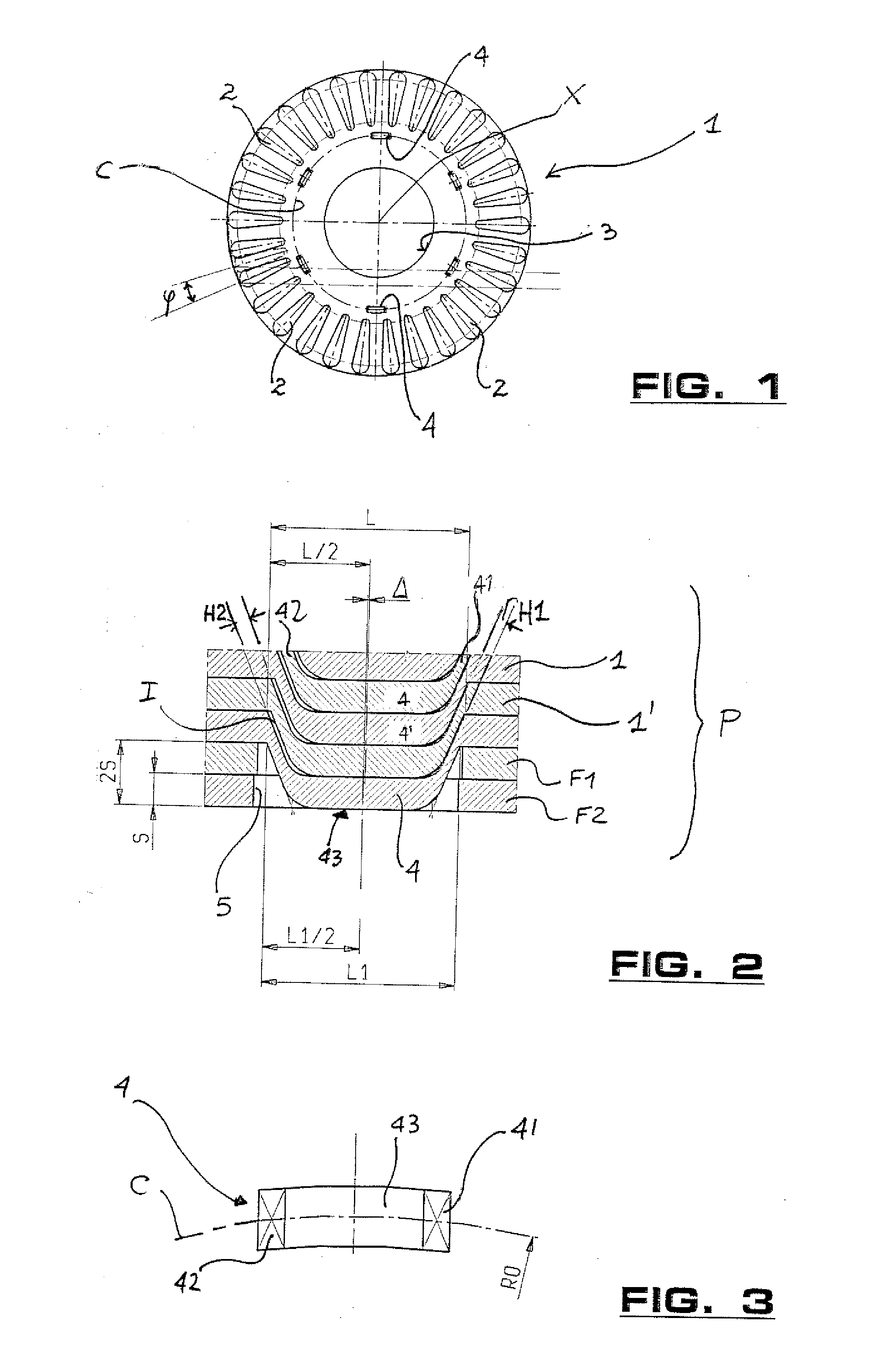
[0039]With reference to FIG. 1, a lamination 1 is shown according to the present invention. The lamination 1 can be stacked to form a lamination pack used for making rotors of electric motors. The lamination 1 has a substantially circular shape, and is symmetrical relative to the axis of rotation X. A hole 3 is provided in the middle portion of the lamination 1 to allow for coupling to a shaft.

[0040]The lamination 1 is provided with a plurality of slots 2 that are intended to form, along with the slots 2 of the other laminations 1 in the same pack, the slots for housing the rotor windings. Particularly, the rotor slots are either skew slots, or have a helical development. When the laminations 1 have been stacked, the slots are filled with a molten material, generally (die-cast) aluminium.

[0041]The laminations 1 are stacked with an angular offset being provided between two adjoining laminations 1. In other words, in order to obtain skew or helical slots, the slots 2 of a first lamina...


PUM

PropertyMeasurementUnit
Thicknessaaaaaaaaaa
Angleaaaaaaaaaa

Abstract

The present invention relates to a stackable lamination for rotors of electric motors having inclined or helical slots, and a method for manufacturing the lamination. The lamination comprises at least one boss projecting from a face thereof for coupling with a second lamination in the same pack. The two coupled laminations are rotated according to an offset angle. Advantageously, a boss portion has a lower thickness than the remaining portions to allow the same boss to be coupled with a matching boss of the second lamination, the two coupled bosses being angularly offset according to a preset angle. The reduction in the boss thickness is carried out during the manufacturing step of the lamination.

Description

BACKGROUND OF THE INVENTION[0001]1. Field of the Invention[0002]The present invention relates to a lamination for electric motors and a method for making this lamination and coupling more laminations to each other.[0003]2. Discussion of Related Art[0004]The stators and rotors of several types of electric motors are made by packing a plurality of suitably shaped laminations made of ferromagnetic material. The individual laminations are generally obtained from metal laminates that are subjected to pressing and punching processes.[0005]The thus-obtained laminations are coupled to each other; in particular, they are stacked to form the core of a rotor or to form a stator. Each lamination is provided with slots, which along with the slots of the other laminations define the slots suitable to house the stator / rotor windings or the melt material alternatively used (generally die-cast aluminium).[0006]The laminations used for making rotors of electric motors can be coupled such that the rot...

Claims


Application Information

Patent Timeline
IPC IPC(8): H01F3/04
CPCH02K1/26H02K15/024H02K2201/06Y10T29/49009Y10T29/49002Y10T29/49012Y10T29/49078H02K2201/09
Inventor MALVESTITI, ALBERTOMALVESTITI, CLAUDIOCONFALONIERI, SERGIO
Owner ERNESTO MALVESTITI
Why Eureka
Try Eureka