
Cell container and battery
a cell container and battery technology, applied in the direction of secondary cell servicing/maintenance, cell components, sustainable manufacturing/processing, etc., can solve the problems of performance degradation, difficult heat generated by the battery to radiate to the outside, and the method is problematic, so as to improve the vibration resistance and shock resistance, maintain the battery performance, and ensure the effect of reliability
- Summary
- Abstract
- Description
- Claims
- Application Information
AI Technical Summary
Benefits of technology
Problems solved by technology
Method used
Image

Examples
first embodiment
[0076]Hereunder is a description of the battery pack according to a first embodiment of the present invention, with reference to FIG. 1 through FIG. 6.
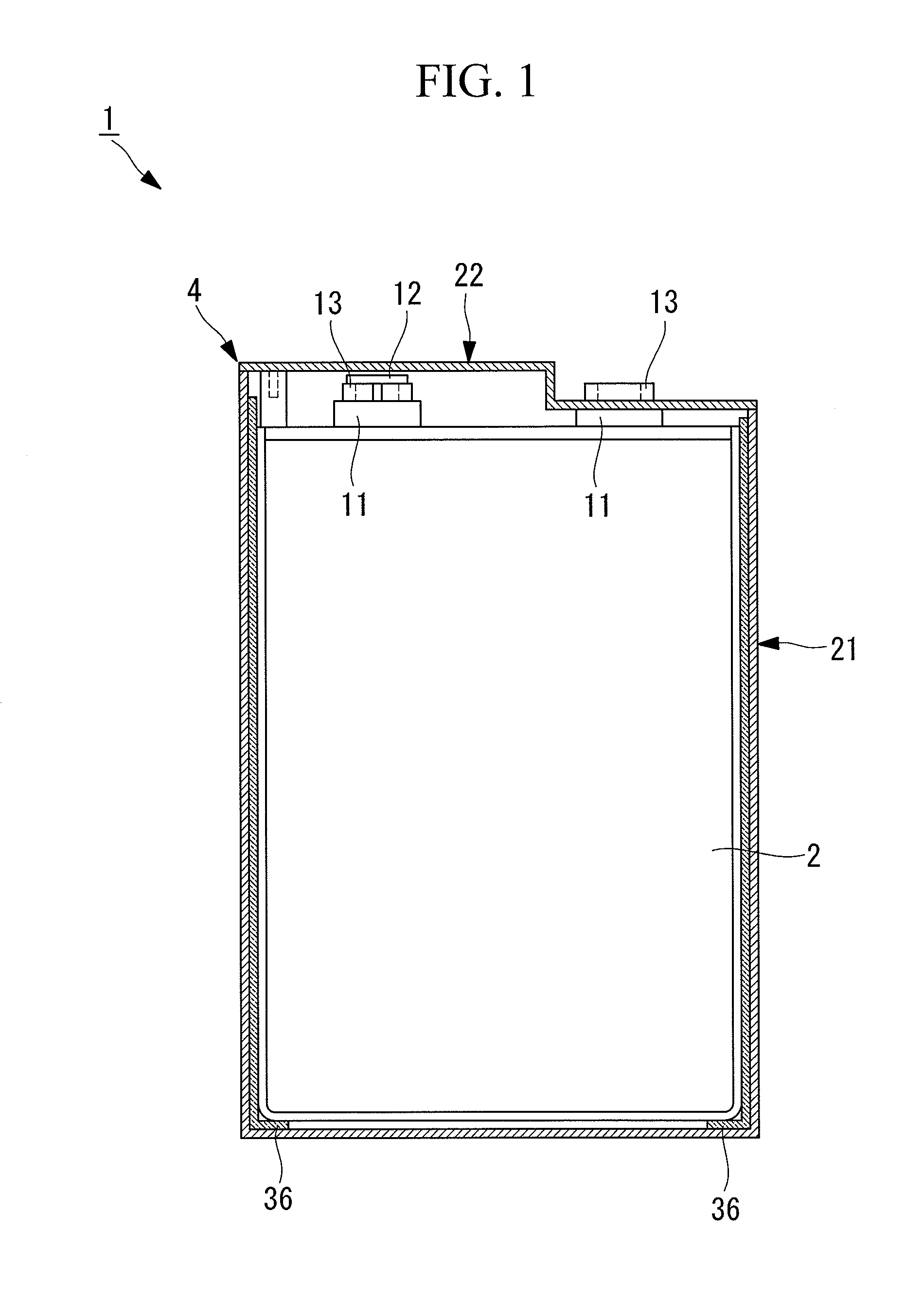
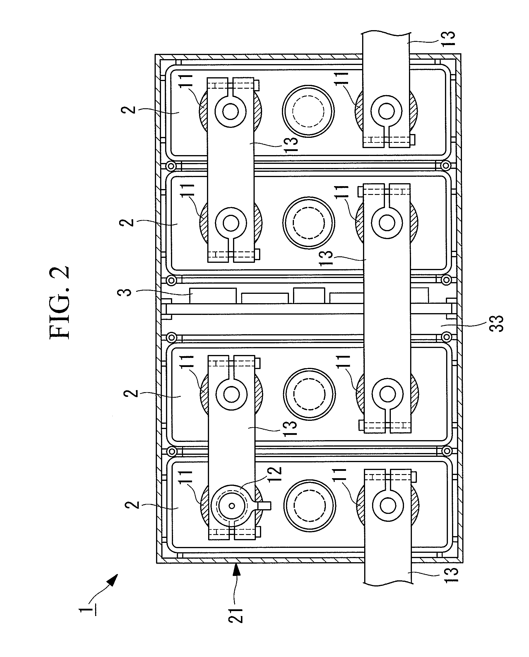
[0077]FIG. 1 is a side cross-sectional view which illustrates the structure of the battery pack according to this embodiment. FIG. 2 is a top plan view which illustrates the inner structure of the battery pack of FIG. 1.
[0078]The battery pack 1 of this embodiment is a battery pack comprising a plurality of unit cells 2 which are chargeable and dischargeable secondary cells. This battery pack 1 is used as a power source of a mobile object such as a deep ocean research vehicle and an electric car, or used for a power storage system, an uninterruptible power supply system, or such applications.
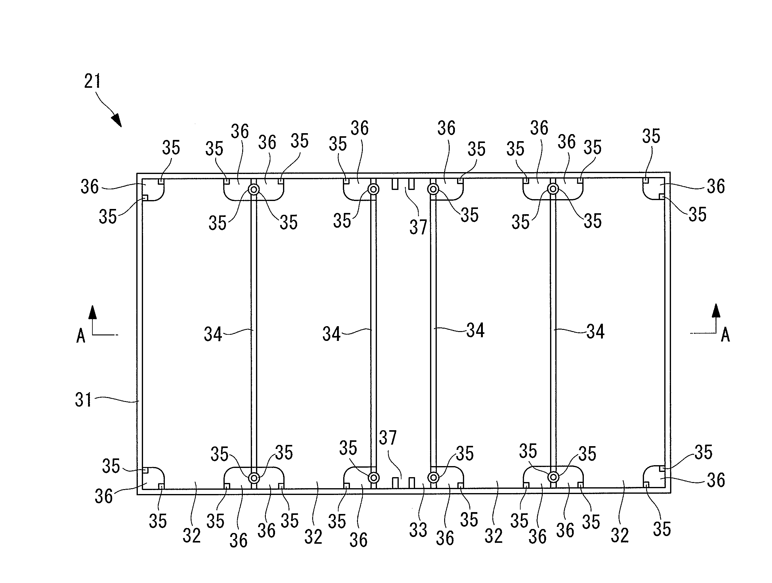
[0079]As shown in FIG. 1 and FIG. 2, the battery pack 1 comprises the unit cells 2 such as lithium ion secondary cells, a controller 3 for controlling the unit cells 2, and a cell container 4 in which the unit cells 2 and the controller 3 are place...
second embodiment
[0110]Next is a description of a second embodiment of the present invention with reference to FIG. 8 through FIG. 11.
[0111]The basic structure of the battery pack of this embodiment is the same as that of the first embodiment; however, this embodiment is different from the first embodiment regarding the method of fixing the unit cells. In this embodiment, therefore, the description is made only for the method of fixing the unit cells with reference to FIG. 8 through FIG. 11, and the description of other components is omitted.
[0112]FIG. 8 is a side cross-sectional view which illustrates the structure of the battery pack according to this embodiment. FIG. 9 is a top plan view which illustrates the inner structure of the battery pack of FIG. 8.
[0113]The same reference symbols are used for components the same as those in the first embodiment, and the description thereof is omitted.
[0114]As shown in FIG. 8 and FIG. 9, the battery pack 101 comprises unit cells 2 such as lithium ion second...
third embodiment
[0125]Next is a description of a third embodiment of the present invention with reference to FIG. 12 through FIG. 14.
[0126]The basic structure of the battery pack of this embodiment is the same as that of the first embodiment; however, this embodiment is different from the first embodiment regarding the structure of the upper case. In this embodiment, therefore, the description is made only for the structure of the upper case with reference to FIG. 12 through FIG. 14, and the description of other components is omitted.
[0127]FIG. 12 is a side cross-sectional view which illustrates the structure of the battery pack according to this embodiment.
[0128]The same reference symbols are used for components the same as those in the first embodiment, and the description thereof is omitted.
[0129]As shown in FIG. 12, the battery pack 201 comprises unit cells 2 such as lithium ion secondary cells, a controller 3 for controlling the unit cells 2, and a cell container 204 in which the unit cells 2 ...
PUM
| Property | Measurement | Unit |
|---|---|---|
| voltage | aaaaa | aaaaa |
| temperature | aaaaa | aaaaa |
| elastic | aaaaa | aaaaa |
Abstract
Description
Claims
Application Information