Structure for fixing flexible wiring board

Inactive Publication Date: 2010-08-12
MITSUBISHI ELECTRIC CORP
View PDF3 Cites 27 Cited by
  • Summary
  • Abstract
  • Description
  • Claims
  • Application Information

AI Technical Summary

Benefits of technology

[0007]According to the present invention, it is arranged that the flexible wiring board is provided with the lock member, wherein the lock member is fit in the opening of the stationary board in a state where the terminal section of the flexible wiring board is connected and secured to th

Problems solved by technology

Conventionally, in the connection using a flexible wiring board (flexible printed circuit board, hereinafter referred to as an “FPC”), when an FPC is inserted into a connector provided on an electronic component or a circuit board and fixed thereto, the FPC is sometimes fixed thereto with the FPC curved or with the FPC inserted insufficiently into the interior of the connector, and thus the FPC occasionally causes failure in an apparatus using the FPC.
Further, since the connector is provided with a pawl for locking the FPC thereto, the area of the end face thereof where positioning is possible is limited.
Thu

Method used


Image

  • Structure for fixing flexible wiring board
  • Structure for fixing flexible wiring board
  • Structure for fixing flexible wiring board

Examples


first embodiment

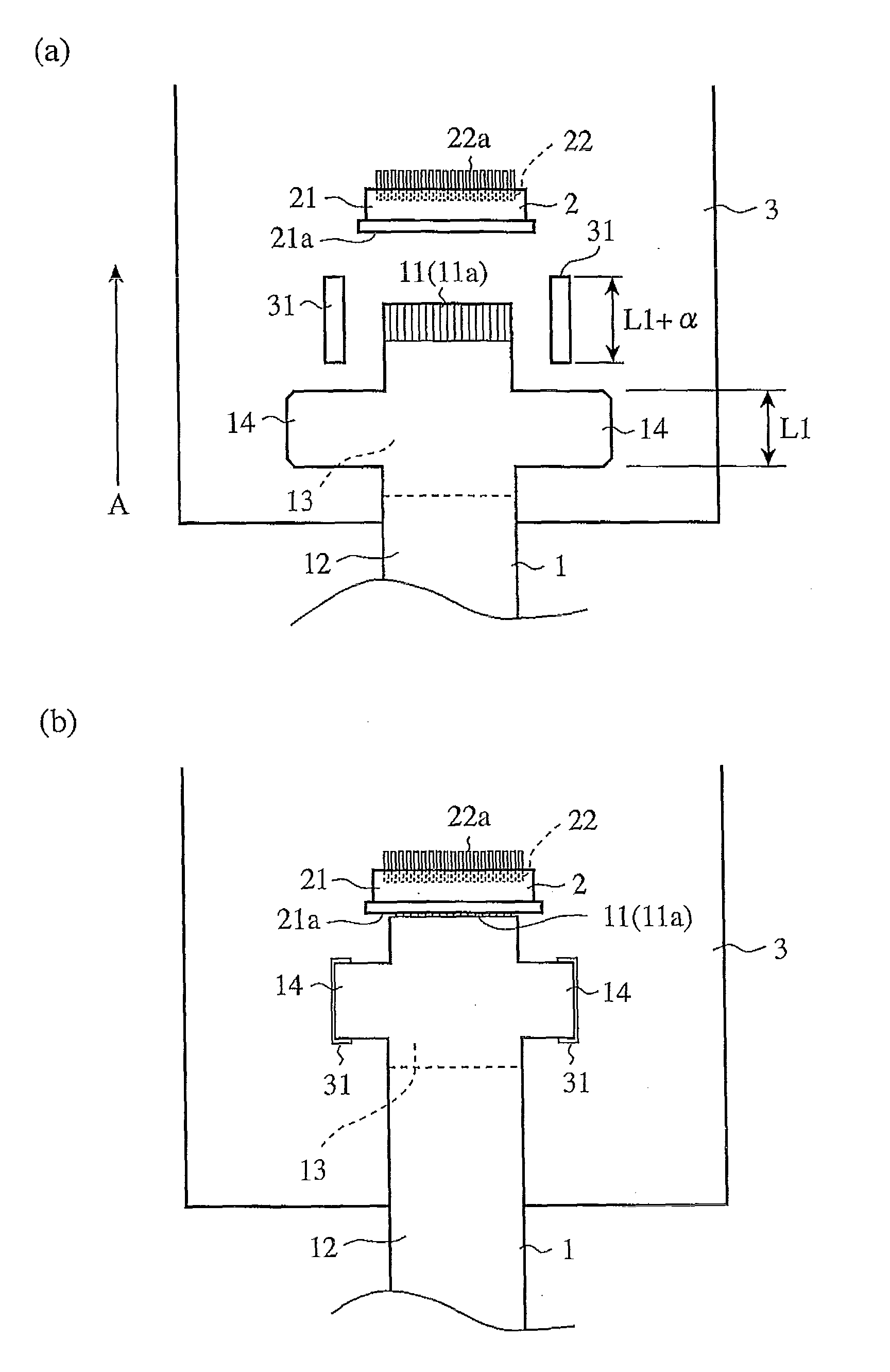
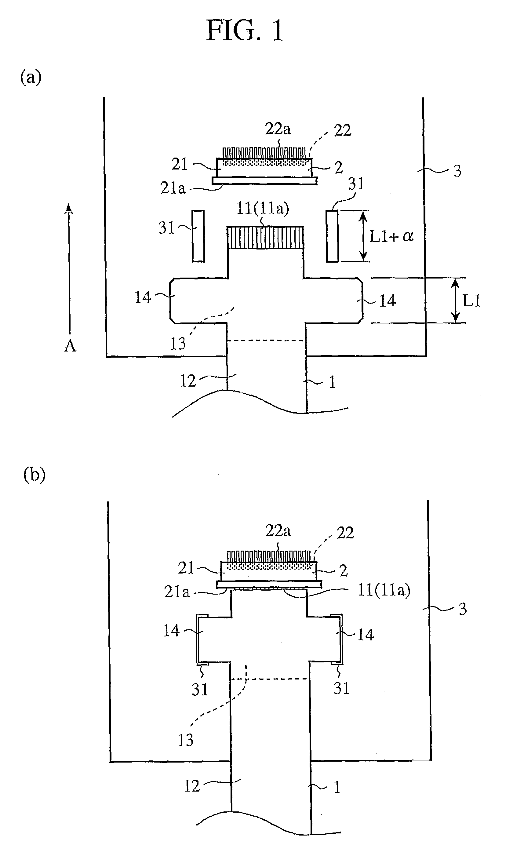
[0020]FIG. 1 is a front view showing a composition of a fixing structure of an FPC in accordance with the first embodiment of the present invention, FIG. 1(a) is a view showing a state before an FPC is fixed, and FIG. 1(b) is a view showing a state after an FPC has been fixed. An FPC (flexible wiring board) 1 is composed of a conductor 11, an insulating member 12, and a reinforcing board (reinforcing member) 13, and inserted into a connector 2 provided on a board (stationary board) 3 to be electrically connected with the board 3. The conductor 11 as a wiring pattern is disposed within the flexible insulating member 12; however, at the one end of the FPC 1, the insulating member 12 is striped to expose the conductor 11, thus forming a connection terminal section 11a to be connected to the connector 2. Further, the insulating member 12 has a pair of rectangular lock members 14 projecting in a substantially orthogonal direction to the direction of inserting the FPC 1 into the connector...

second embodiment

[0029]FIG. 3 is a front view showing a composition of a fixing structure of an FPC in accordance with the second embodiment of the present invention.

[0030]In this fixing structure, an FPC has a shoulder portion wider than the width of the tip portion of a lock member in the basal portion of each of the lock members which is explained in the fixing structure of an FPC in accordance with the first embodiment shown in FIG. 1. Hereinbelow, to the same parts as the constituent elements of the fixing structure of an FPC in accordance with the first embodiment, the same numerals as those used in the first embodiment are provided and its explanation are omitted or simplified.

[0031]An FPC 1 is composed of a conductor 11, an insulating member 12, and a reinforcing board 13. The insulating member 12 and the reinforcing board 13 has a pair of lock members 15 projecting in a generally orthogonal direction to the direction of arrow A indicating the inserting direction of the FPC 1 into the connec...

third embodiment

[0036]FIG. 5 is a view showing a composition of an FPC in accordance with the third embodiment of the present invention, FIG. 5(a) is a front view showing the composition of the back of the FPC, and FIG. 5(b) is a side view thereof.

[0037]In the fixing structure of an FPC, a lock member projecting from the end of a reinforcing board in the inserting direction of an FPC is employed, instead of the lock member of the fixing structure of an FPC in accordance with the first embodiment shown in FIG. 1 projecting from the insulating member and the reinforcing member in a direction substantially orthogonal to the inserting direction of the FPC. Hereinbelow, to the same parts as the constituent elements of the fixing structure of an FPC in accordance with the first embodiment, the same numerals as those used in the first embodiment are provided and their explanations are omitted or simplified.

[0038]An insulating reinforcing board 13 is bonded in the vicinity of the connection terminal sectio...


PUM


Abstract

A flexible wiring board 1 includes an insulating member 12 having a conductor 11 formed therein, a reinforcing board 13 for reinforcing the insulating member 12 in the vicinity of the connection terminal 11a of the flexible wiring board 1, and a lock member 14 to be locked to a board 3 having a connector 2, with the board 3 having an opening 31 for receiving the lock member 14 fit therein in a state where the connection terminal 11a is connected and secured to the connector 2.

Description

TECHNICAL FIELD[0001]The present invention relates to a fixing structure of a flexible wiring board (FPC) for establishing an electric connection between electronic components or circuit boards.BACKGROUND ART[0002]Conventionally, in the connection using a flexible wiring board (flexible printed circuit board, hereinafter referred to as an “FPC”), when an FPC is inserted into a connector provided on an electronic component or a circuit board and fixed thereto, the FPC is sometimes fixed thereto with the FPC curved or with the FPC inserted insufficiently into the interior of the connector, and thus the FPC occasionally causes failure in an apparatus using the FPC. For preventing such failures, e.g., in Patent Document 1, an FPC has integrally formed a square-frame-shaped guide made of a flexible insulating member such that the guide encloses the periphery of the exposed ends of conductors which are provided in a row on the FPC. The guide is provided, around the periphery of the expose...

Claims


Application Information

Patent Timeline
IPC IPC(8): H05K1/14
CPCH05K1/0281H05K1/118H05K1/147H05K3/0058H05K2201/048H05K2201/2009H05K2201/09109H05K2201/09145H05K2201/10189H05K2201/10446H05K2201/10598H05K2201/09063
Inventor NAGAMI, TETSUROSERIZAWA, SHINJIYASUI, YOICHI
Owner MITSUBISHI ELECTRIC CORP
Why Eureka
Try Eureka