Plasma Clearance Controlled Compressor

a compressor and plasma technology, applied in the direction of machines/engines, mechanical equipment, liquid fuel engines, etc., can solve the problems of compressor system stall, compressor blade tip vortices, and high stall margin requirements

Inactive Publication Date: 2010-11-11
GENERAL ELECTRIC CO
View PDF18 Cites 28 Cited by
  • Summary
  • Abstract
  • Description
  • Claims
  • Application Information

AI Technical Summary

Benefits of technology

[0006]The above-mentioned need or needs may be met by exemplary embodiments which provide a plasma leakage flow control system for a compressor, comprising a circumferential row of compressor blades, an annular casing surrounding the tips of the blades, located radially apart from the tips of the blades and at least one annular plasma generator located on

Problems solved by technology

The conflicting requirements of stall margin and efficiency are particularly demanding in high performance jet engines that operate under operating conditions such as severe inlet distortions and increased auxiliary power extractions, while still requiring high a level of stall margin in conjunction with high compression efficiency.
Compressor system

Method used


Image

  • Plasma Clearance Controlled Compressor
  • Plasma Clearance Controlled Compressor
  • Plasma Clearance Controlled Compressor

Examples


Embodiment Construction

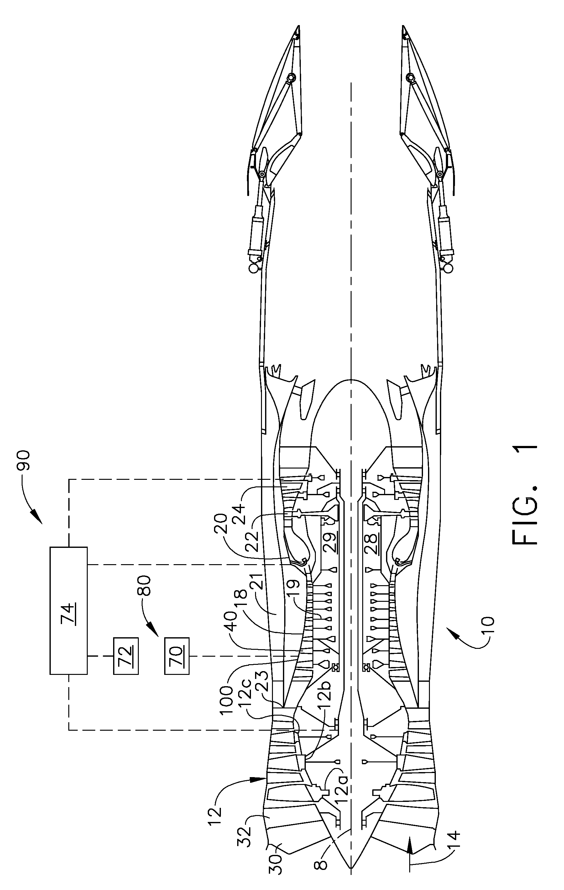
[0021]Referring to the drawings wherein identical reference numerals denote the same elements throughout the various views, FIG. 1 shows an exemplary turbofan gas turbine engine 10 incorporating an exemplary embodiment of the present invention. It comprises an engine centerline axis 8, fan 12 which receives ambient air 14, a booster or low pressure compressor (LPC) 16, a high pressure compressor (HPC) 18, a combustor 20 which mixes fuel with the air pressurized by the HPC 18 for generating combustion gases or gas flow which flows downstream through a high pressure turbine (HPT) 22, and a low pressure turbine (LPT) 24 from which the combustion gases are discharged from the engine 10. The HPT 22 is joined to the HPC 18 to substantially form a high pressure rotor 29. A low pressure shaft 28 joins the LPT 24 to both the fan 12 and the booster 16. The second or low pressure shaft 28 is rotatably disposed co-axially with and radially inwardly of the first or high pressure rotor.

[0022]The ...


PUM


Abstract

A plasma leakage flow control system for a compressor is disclosed, comprising a circumferential row of compressor blades, an annular casing surrounding the tips of the blades, located radially apart from the tips of the blades and at least one annular plasma generator located on the annular casing. The annular plasma generator comprises an inner electrode and an outer electrode separated by a dielectric material. A gas turbine engine having a plasma leakage flow control system further comprises an engine control system which controls the operation of the annular plasma generator such that the blade tip leakage flow can be changed.

Description

BACKGROUND OF THE INVENTION[0001]This invention relates generally to gas turbine engines, and, more specifically, to the enhancement of stable flow range of compression systems therein, such as fans, boosters and compressors using plasma actuators.[0002]In a turbofan aircraft gas turbine engine, air is pressurized in a fan module, a booster module and a compression module during operation. The air passing through the fan module is mostly passed into a by-pass stream and used for generating the bulk of the thrust needed for propelling an aircraft in flight. The air channeled through the booster module and compression module is mixed with fuel in a combustor and ignited, generating hot combustion gases which flow through turbine stages that extract energy therefrom for powering the fan, booster and compressor rotors. The fan, booster and compressor modules have a series of rotor stages and stator stages. The fan and booster rotors are typically driven by a low pressure turbine and the...

Claims


Application Information

Patent Timeline
IPC IPC(8): F01D11/08
CPCF05D2270/172F01D11/20F04D29/687F04D29/164
Inventor WADIA, ASPI RUSTOMCLARK, DAVID SCOTTLEE, CHING-PANGBREEZE-STRINGFELLOW, ANDREWMCNULTY, GREGORY SCOTT
Owner GENERAL ELECTRIC CO
Why Eureka
Try Eureka