Beverage bottle filling plant with a beverage bottle labeling machine, and a cutting arrangement for a beverage bottle labeling machine

a beverage bottle and labeling machine technology, applied in the direction of liquid handling, packaging goods, transportation and packaging, etc., can solve the problems of increasing wear or deterioration of the blade elements, time-consuming, and difficult adjustment of the cutting gap, so as to achieve precise or substantially precise alignment, different hardnesses and/or wear resistan

Inactive Publication Date: 2010-12-02
KHS GMBH
View PDF32 Cites 2 Cited by
  • Summary
  • Abstract
  • Description
  • Claims
  • Application Information

AI Technical Summary

Benefits of technology

[0014]It is an object of the present application to provide a cutting device which avoids, restricts, and / or minimizes the aforementioned disadvantages, in one possible embodiment avoiding, restricting, or minimizing a time-consuming adjusting of the cutting gap.
[0015]An object of the present application is to create a cutting device which, while preserving the advantageous self-resharpening of such a device, significantly improves the wear strength and thus the useful life of the blades used, and thus in turn the number of cuts that can be executed between two adjustment processes.SUMMARY
[0017]A characteristic of the present application is not producing the two cutting edges that form the cutting gap from the same material, but selecting such a material pairing so that the two cutting edges have different hardnesses and / or wear resistances. In this case, it is possible that when one of the two cutting edges forming the respective cutting gap is created or re-sharpened in an appropriate manner primarily by the other cutting edge through material removal so that when the cutting device is setup, i.e. during a first commissioning or during a recommissioning of the cutting device after operating elements, e.g. the blade elements, have been exchanged, a rough adjusting of the blade element one relative to the other, but no time-consuming, precise or substantially precise aligning is necessary or may be desired.

Problems solved by technology

Each contact of the cutting edges during the adjustment procedure or during the cutting procedure leads to increased wear or to a deterioration in the blade elements.
For example where the label material is very thin, for example a material thickness of 4 / 100 of a millimeter (0.25 mm) or less as is usual for, among other things, label materials for foil labels, the adjusting of the cutting gap is extremely difficult and time-consuming, and may be carried out in a reliable manner exclusively by highly-qualified specialist personnel.

Method used


Image

  • Beverage bottle filling plant with a beverage bottle labeling machine, and a cutting arrangement for a beverage bottle labeling machine
  • Beverage bottle filling plant with a beverage bottle labeling machine, and a cutting arrangement for a beverage bottle labeling machine
  • Beverage bottle filling plant with a beverage bottle labeling machine, and a cutting arrangement for a beverage bottle labeling machine

Examples


Embodiment Construction

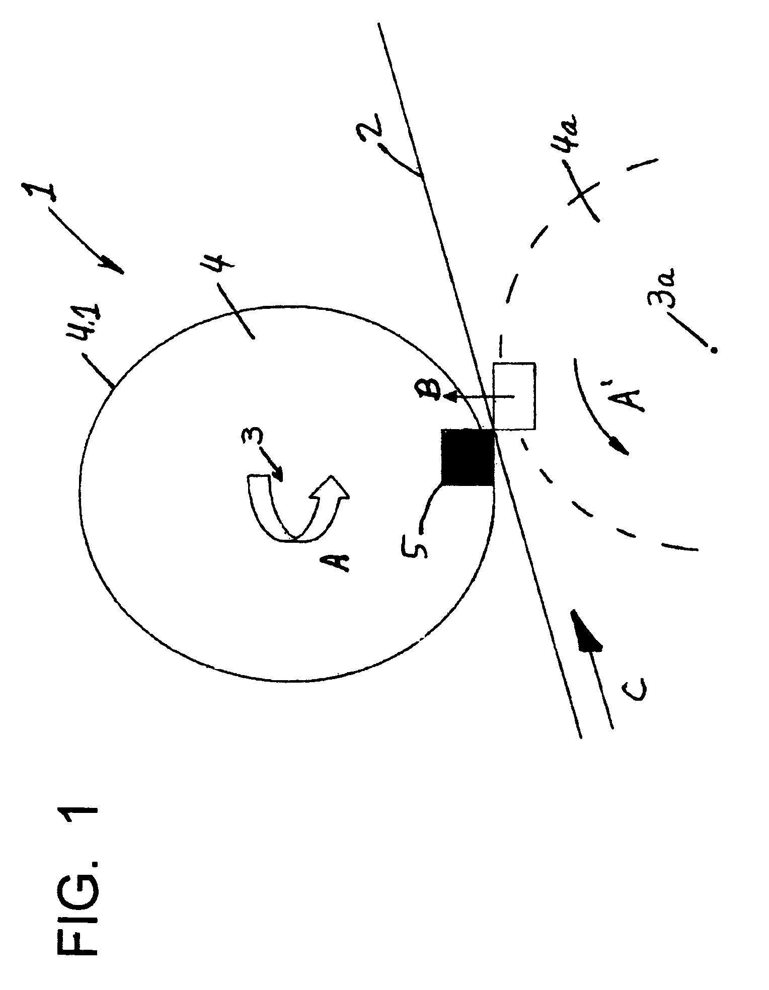
[0026]The reference 1 in FIG. 1 is given to a cutting device for cutting a strip-shaped or web-shaped flat material 2, for example a label material with a maximum thickness of 4 / 100 of a millimeter (0.25 mm) or less, i.e. for the separating of individual labels from the material 2.

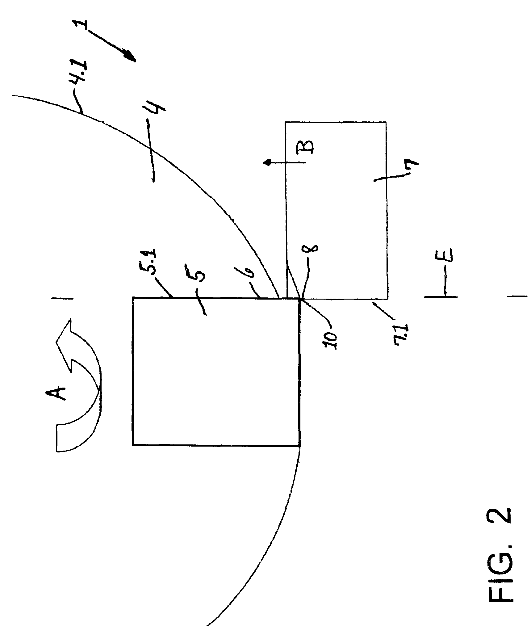
[0027]The cutting device 1 essentially comprises a machine element 4 that is driven in a rotating manner about a vertical or substantially vertical machine axis 3 in the direction of the arrow A, said machine element having, for example, a peripheral surface or outer surface 4.1 that surrounds the vertical or substantially vertical machine axis 3 in a circular cylindrical manner and being provided, for example, so as to be exchangeable and adjustable on the peripheral surface or outer surface 4.1 with at least one blade element 5, in such a manner that the blade element 5 forms a cutting edge 6 on a region protruding beyond the outer surface 4. In the case of the specific embodiment represented, the cuttin...


PUM

PropertyMeasurementUnit
hardnessaaaaaaaaaa
widthaaaaaaaaaa
thicknessaaaaaaaaaa

Abstract

A cutting device and method for operating a cutting device. The abstract of the disclosure is submitted herewith as required by 37 C.F.R. §1.72(b). As stated in 37 C.F.R. §1.72(b): A brief abstract of the technical disclosure in the specification must commence on a separate sheet, preferably following the claims, under the heading “Abstract of the Disclosure.” The purpose of the abstract is to enable the Patent and Trademark Office and the public generally to determine quickly from a cursory inspection the nature and gist of the technical disclosure. The abstract shall not be used for interpreting the scope of the claims. Therefore, any statements made relating to the abstract are not intended to limit the claims in any manner and should not be interpreted as limiting the claims in any manner.

Description

CONTINUING APPLICATION DATA[0001]This application is a Continuation-In-Part application of International Patent Application No. PCT / EP2008 / 009757, filed on Nov. 18, 2008, which claims priority from Federal Republic of Germany Patent Application No. 10 2007 057 409.8, filed on Nov. 27, 2007. International Patent Application No. PCT / EP2008 / 009757 was pending as of the filing date of this application. The United States was an elected state in International Patent Application No. PCT / EP2008 / 009757.BACKGROUND[0002]1. Technical Field[0003]The present application relates to a cutting device, for example a cutting device of a labeling machine. The cutting device having a machine element that is driven in a rotating manner about a machine axis. The cutting device also comprises at least one first blade element that forms a first cutting edge and is provided at the machine element. The first blade element, when the machine element is rotating, may interact with a second cutting edge of at lea...

Claims


Application Information

Patent Timeline
Patent Type & Authority Applications(United States)
IPC IPC(8): B65B3/02B65B61/00
CPCB26D1/626B26D2001/0066B26D1/0006B65C2009/1861B26D2001/002B65C2009/1838B65C9/1803
Inventor KRAMER, KLAUSDECKERT, LUTZKRESS, OLIVER
Owner KHS GMBH
Why Eureka
Try Eureka