Image display system, image display apparatus, image providing apparatus and method thereof

a technology of image display system and image providing apparatus, which is applied in the direction of television system, static indicating device, instruments, etc., can solve the problem of requiring a large amount of time for accessing multimedia data

Inactive Publication Date: 2011-03-10
EMPIRE TECH DEV LLC
View PDF3 Cites 10 Cited by
  • Summary
  • Abstract
  • Description
  • Claims
  • Application Information

AI Technical Summary

Benefits of technology

Significant improvements have been made in the CPU capability and the storage capacity of mobile devices such as mobile phones and PDAs (personal digital assistants), thereby enabling saving and operating multimedia data such as images and music in the mobile devices.

Problems solved by technology

However, since such mobile devices generally lack sufficient computational resources as compared to conventional computer systems, accessing multimedia data requires a large amount of time.

Method used


Image

  • Image display system, image display apparatus, image providing apparatus and method thereof
  • Image display system, image display apparatus, image providing apparatus and method thereof
  • Image display system, image display apparatus, image providing apparatus and method thereof

Examples


first embodiment

Next, a first embodiment of the disclosure of the present application will be described.

[Image Providing Server Program 20]

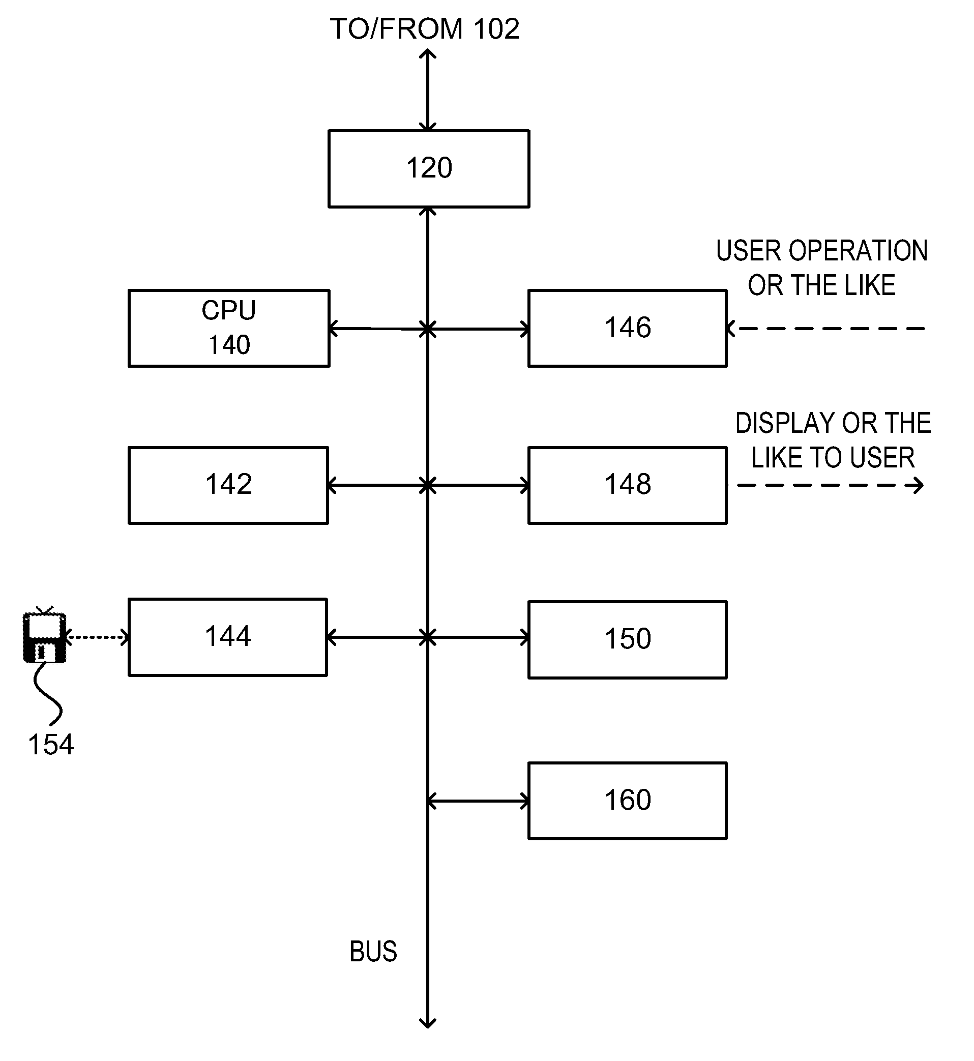
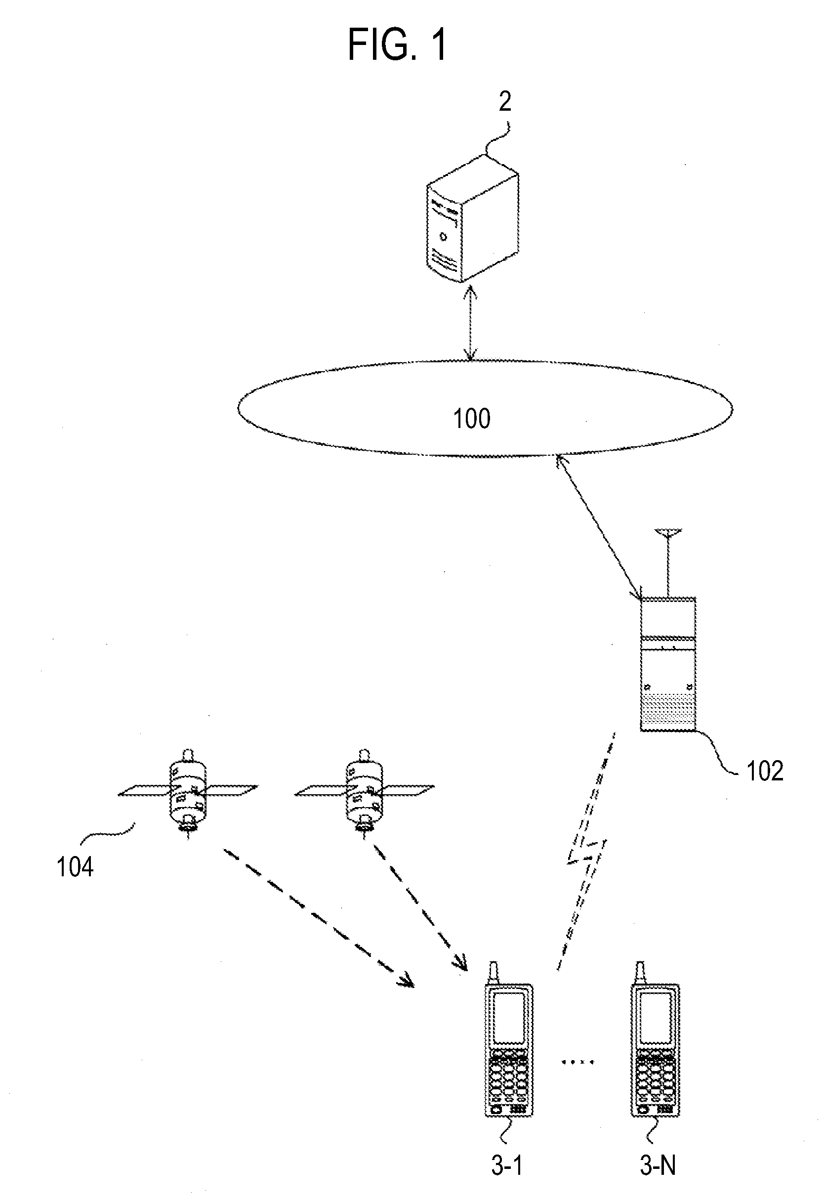
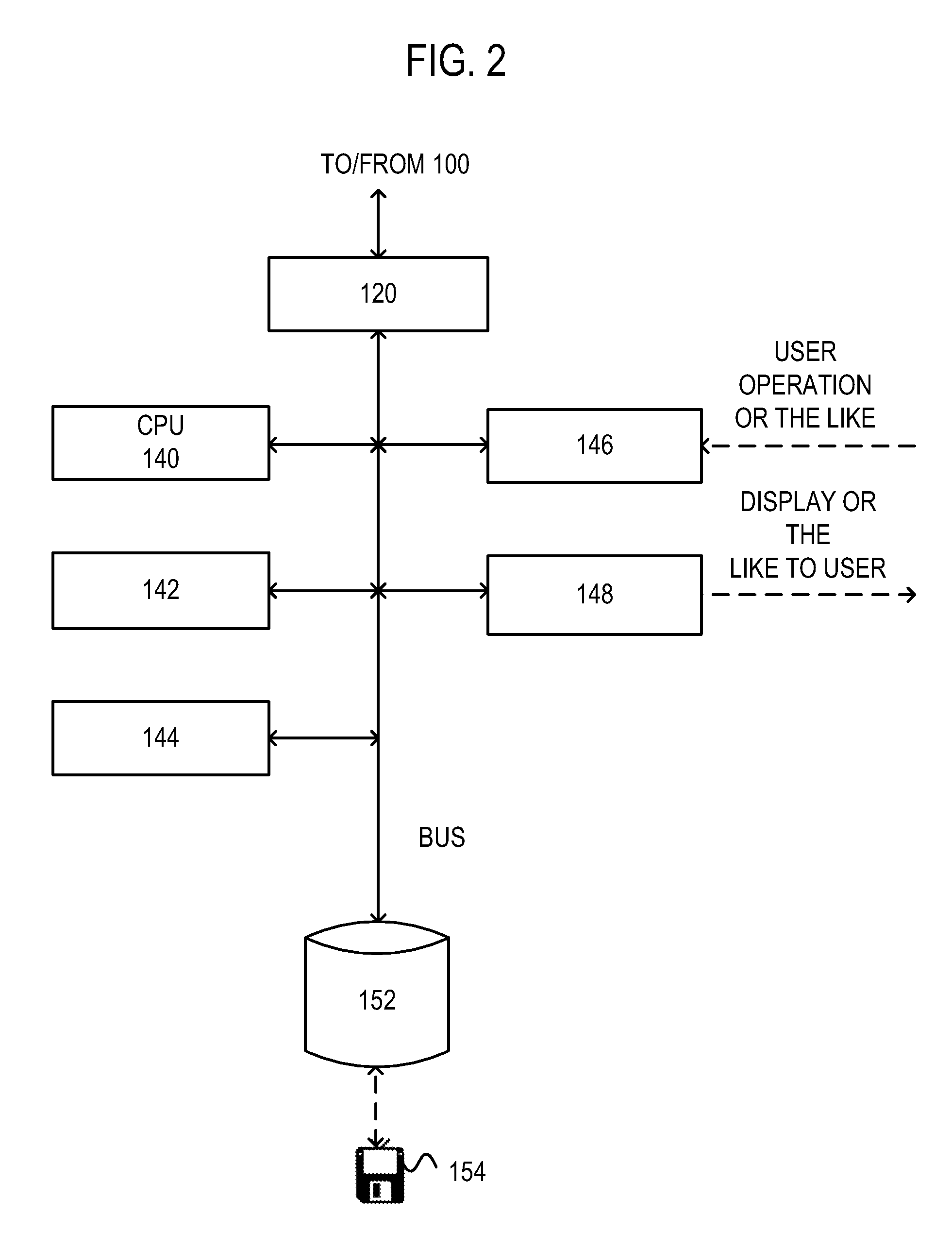
FIG. 4 is a diagram illustrating an image providing server program 20 to be executed at the image providing server 2 illustrated in FIGS. 1 and 2.

As illustrated in FIG. 4, the image providing server program 20 includes a communication processing unit 200, a user interface unit (UI) 202, an image receiving unit 204, an image information managing unit 206, an image database (DB) 208, an image inputting unit 210, an image request receiving unit 212, and an image transmitting unit 214.

The image providing server program 20 is loaded on to the memory 142 of the image providing server 2 via the recording medium 154 (FIGS. 2 and 3), the network 100 and the like, and is executed specifically using hardware resources of the image providing server 2 on an OS (not illustrated) that runs on the image providing server 2 (the same logic will apply to the following programs and...

second embodiment

Next, a second embodiment of the disclosure of the present application will be described.

[Image Providing Server Program 22]

FIG. 11 is a diagram illustrating a second image providing server program 22 to be executed at the image providing server 2 illustrated in FIGS. 1 and 2 in place of the image providing server program 20.

As illustrated in FIG. 11, the second image providing server program 22 is made up of a communication processing unit 200, an image information managing unit 222, an image database (DB) 224, an analytical precision calculating module 24, an image analyzing module 26, an image providing module 28, an image selection receiving unit 292, and a detailed image data transmitting unit 294.

Using these components, the image providing server program 22 calculates an analytical precision of an image so as to satisfy a designated restrictive condition, and analyzes one or more images at the calculated analytical precision.

In addition, when displaying a designated image amon...

third embodiment

Next, a third embodiment of the disclosure of the present application will be described.

A program that is substantially the same as the image providing server program 20 described earlier is to be executed at an image providing server 2 according to the third embodiment.

[Terminal Program 50]

FIG. 14 is a diagram illustrating a third terminal program 50 to be executed at the terminal 3 illustrated in FIGS. 1 and 3.

As illustrated in FIG. 14, the third terminal program 50 includes a communication processing unit 300, a UI 302, an image storing module 32, an detection precision calculating module 52, a detecting module 54, an image providing module 56, an image selecting unit 392, and a detailed image display processing unit 394.

Using these components, the terminal program 50 calculates a detection precision for detecting a detection target from each piece of image information so as to satisfy a designated restrictive condition, performs image processing on each piece of image informatio...


PUM


Abstract

An image display apparatus disclosed in the present application is made up of a detection precision calculating module, a detecting module, and an image providing module. The detection precision calculating module calculates a detection precision that satisfies a designated restrictive condition. Based on the calculated detection precision, the detecting module detects a projection of a designated object from each image based on the calculated detection precision, and calculates the number of projections of the designated object included in each image. The image providing module arranges the respective pieces of image information according to the number of detected projections of the object and provides a list of arranged images as a search result.

Description

TECHNICAL FIELDThe present application discloses an image display system, an image display apparatus, an image providing apparatus, and a method thereof.BACKGROUND ARTFor example, Non-Patent Documents 1 and 2 disclose an active meta-level system that dynamically interconnects devices such as databases.Non-Patent Document 1: Shuichi Kurabayashi, Naoki Ishibashi, Yasushi Kiyoki: “Active Multidatabase System for Mobile Computing Environment”, Information Processing Society of Japan SIG Notes 2000-DBS-122, 2000, 463-470.Non-Patent Document 2: Shuichi Kurabayashi, Naoki Ishibashi, Yasushi Kiyoki: A Multidatabase System Architecture for Integrating Heterogeneous Databases with Meta-Level Active Rule Primitives. In Proceedings of the 20th IASTED International Conference on Applied Informatics, 2002, 378-387.DISCLOSURE OF THE INVENTIONMeans for Solving the ProblemsAn image display apparatus disclosed in the present application has been invented in consideration of such background, and an em...

Claims


Application Information

Patent Timeline
Patent Type & Authority Applications(United States)
IPC IPC(8): H04N5/225
CPCG06F17/30247G06K9/00993G06K9/00362G06F16/583G06V40/10G06V10/96
Inventor YOSHIDA, NAOFUMITAKANO, KOSUKEKURABAYASHI, SHUICHI
Owner EMPIRE TECH DEV LLC
Why Eureka
Try Eureka