Swirler with gas injectors

a gas injector and swirler technology, applied in the field of swirlers, can solve the problems of unsteady fluid dynamic processes, thermo-acoustic instabilities, and movement of flames, and achieve the effect of reducing the transport time of free radicals

Inactive Publication Date: 2011-05-05
SIEMENS AG
View PDF9 Cites 13 Cited by
  • Summary
  • Abstract
  • Description
  • Claims
  • Application Information

AI Technical Summary

Benefits of technology

[0045]has the important task to control the size and shape of the recirculation zone as the expansion of the hot gases as a result of combustion reduces transport time of free radicals in the recirculation zone.

Problems solved by technology

The major problems associated with the combustion process in gas turbine engines, in addition to thermal efficiency and proper mixing of the fuel and the air, are associated to flame stabilization, the elimination of pulsations and noise, and the control of polluting emissions, especially nitrogen oxides (NOx), CO, UHC, smoke and particulated emission.
A less stable, easy to move flame front of a pre-mixed flame results in a periodic heat release rate, that, in turn, results in movement of the flame, unsteady fluid dynamic processes, and thermo-acoustic instabilities develop.
When the heat required for reactions to occur is the stability-limiting factor, very small temporal fluctuations in fuel / air equivalence ratios (which could either result either from fluctuation of fuel or air flow through the Burner / Injector) can cause flame to partially extinguish and re-light.
When the flame can, more easily, occur in multiple positions, it becomes more unstable.

Method used


Image

  • Swirler with gas injectors
  • Swirler with gas injectors
  • Swirler with gas injectors

Examples


Embodiment Construction

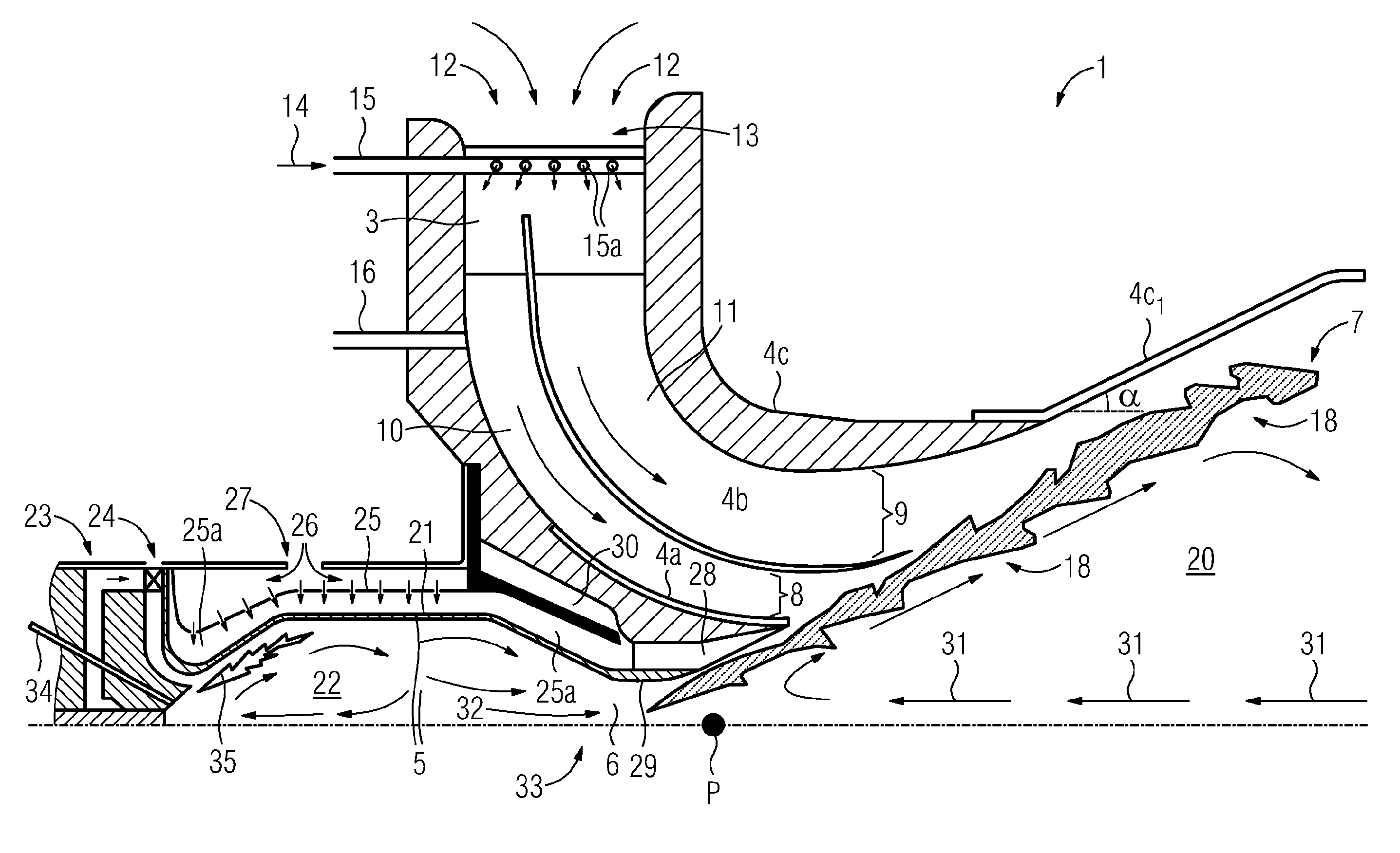
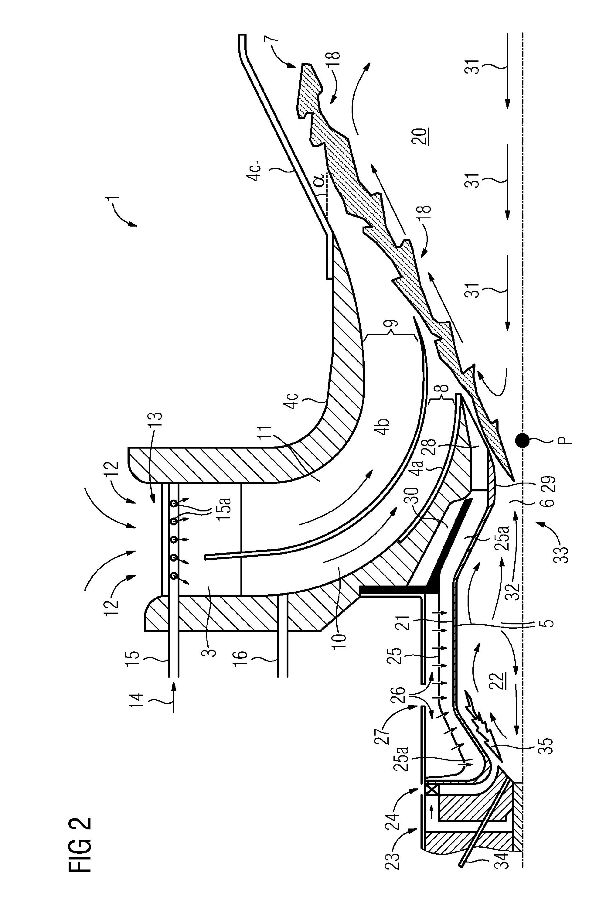
, optimal quarl half angle α should not be smaller then 20 and larger then 25 degrees, allows for a lower swirl before decrease in stability, when compared to a less confined flame front, and[0045]has the important task to control the size and shape of the recirculation zone as the expansion of the hot gases as a result of combustion reduces transport time of free radicals in the recirculation zone.

BRIEF DESCRIPTION OF THE DRAWINGS

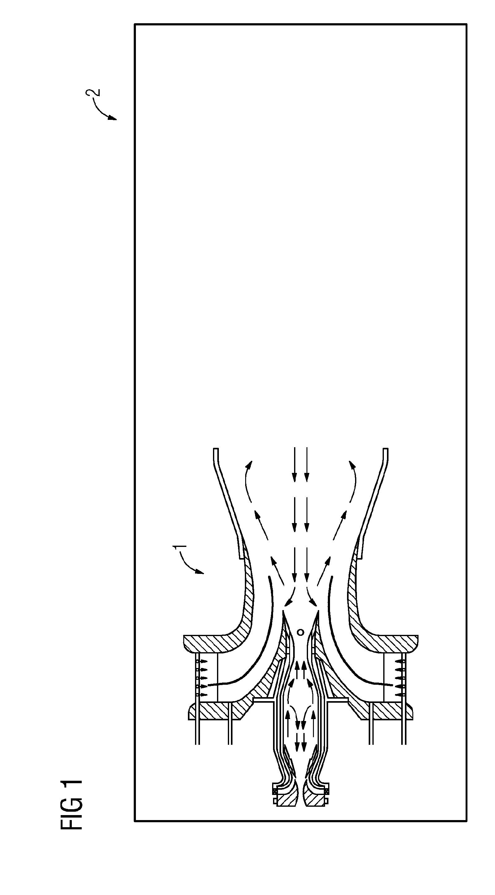
[0046]FIG. 1 is a simplified cross section schematically showing the burner according to the aspects of the invention enclosed in a housing without any details showing how the burner is configured inside said housing.

[0047]FIG. 2 is a cross section through the burner schematically showing a section above a symmetry axis, whereby a rotation around the symmetry axis forms a rotational body displaying a layout of the burner.

[0048]FIG. 3 shows a diagram of stability limits of the flame as a function of the swirl number, imparted level of swirl and equivalence ...


PUM


Abstract

A swirler for premixing a flow of fuel and a flow of air provided to a burner for a gas turbine engine is provided. The burner is provided with a swirler for mixing the air and the fuel and wherein the swirler is provided with swirler wings, wherein a channel formed between two adjacent swirler wings defines a passage. The swirler includes one fuel tube for gaseous fuel positioned in parallel on each side of a mixing rod in the passage, wherein the fuel tubes are provided with a plurality of diffuser holes distributed along the tube acting as gas injectors for efficiently distributing fuel in a flow of air passing through the swirler passage.

Description

CROSS REFERENCE TO RELATED APPLICATIONS[0001]This application is the US National Stage of International Application No. PCT / EP2009 / 053563, filed Mar. 26, 2009 and claims the benefit thereof. The International Application claims the benefits of European Patent Office application No. 08006658.2 EP filed Apr. 1, 2008. All of the applications are incorporated by reference herein in their entirety.TECHNICAL FIELD[0002]The present invention refers to a swirler for use in a burner for a gas turbine engine, and more particularly a swirler having gas injectors for providing a mixture of gas and fuel to a combustion room of a burner of said type.TECHNICAL BACKGROUND[0003]Gas turbine engines are employed in a variety of applications including electric power generation, military and commercial aviation, pipeline transmission and marine transportation. In a gas turbine engine which operates in LPP mode, fuel and air are provided to a burner chamber where they are mixed and ignited by a flame, th...

Claims


Application Information

Patent Timeline
Patent Type & Authority Applications(United States)
IPC IPC(8): B05B7/10
CPCF23C7/004F23C2900/07001F23D14/02F23R3/286F23D2900/14021F23R3/14F23D14/70
Inventor MILOSAVLJEVIC, VLADIMIRPERSSON, ALLANPERSSON, MAGNUS
Owner SIEMENS AG
Why Eureka
Try Eureka