Three-dimensional visual sensor

a three-dimensional and sensor technology, applied in the field of three-dimensional visual sensors, can solve the problems of high possibility of setting the model coordinate system unsuitable for robot control, unsuitable condition, and unsuitable position and attitude, and achieve the effects of enhancing the speed of robot control, facilitating change, and easy correction

Inactive Publication Date: 2011-05-26
ORMON CORP
View PDF3 Cites 25 Cited by
  • Summary
  • Abstract
  • Description
  • Claims
  • Application Information

AI Technical Summary

Benefits of technology

[0018]According to the above aspect, the position of the origin and the direction indicated by each coordinate axis in the projection image are displayed by the specific numerical values using the model coordinate system at the current stage to encourage the user to change the numerical values, so that the model coordinate system and each coordinate of the three-dimensional model can easily be changed.
[0019]According to the present invention, the model coordinate system can easily be corrected to one suitable for the robot control while the setting of the model coordinate system to the three-dimensional model is confirmed. Therefore, the coordinate and angle, outputted from the three-dimensional visual sensor, become suitable for the robot control to be able to enhance the speed of the robot control.

Problems solved by technology

However, the position and the attitude, recognized by the three-dimensional model, are often unsuitable for the condition.
Particularly, when the three-dimensional model is produced using the CAD data, because a definition of the coordinate system determined in the CAD data is directly reflected on the model coordinate system, there is a high possibility of setting the model coordinate system unsuitable for robot control.
As a result, a load on computation of the robot controller is increased to take a long time for the robot control, which results in a problem in that a picking speed is hardly enhanced.
When one of the three-dimensional model and the model coordinate system is unsuitable for the robot control, the user performs manipulation input to change the unsuitable point.

Method used


Image

  • Three-dimensional visual sensor
  • Three-dimensional visual sensor
  • Three-dimensional visual sensor

Examples


Embodiment Construction

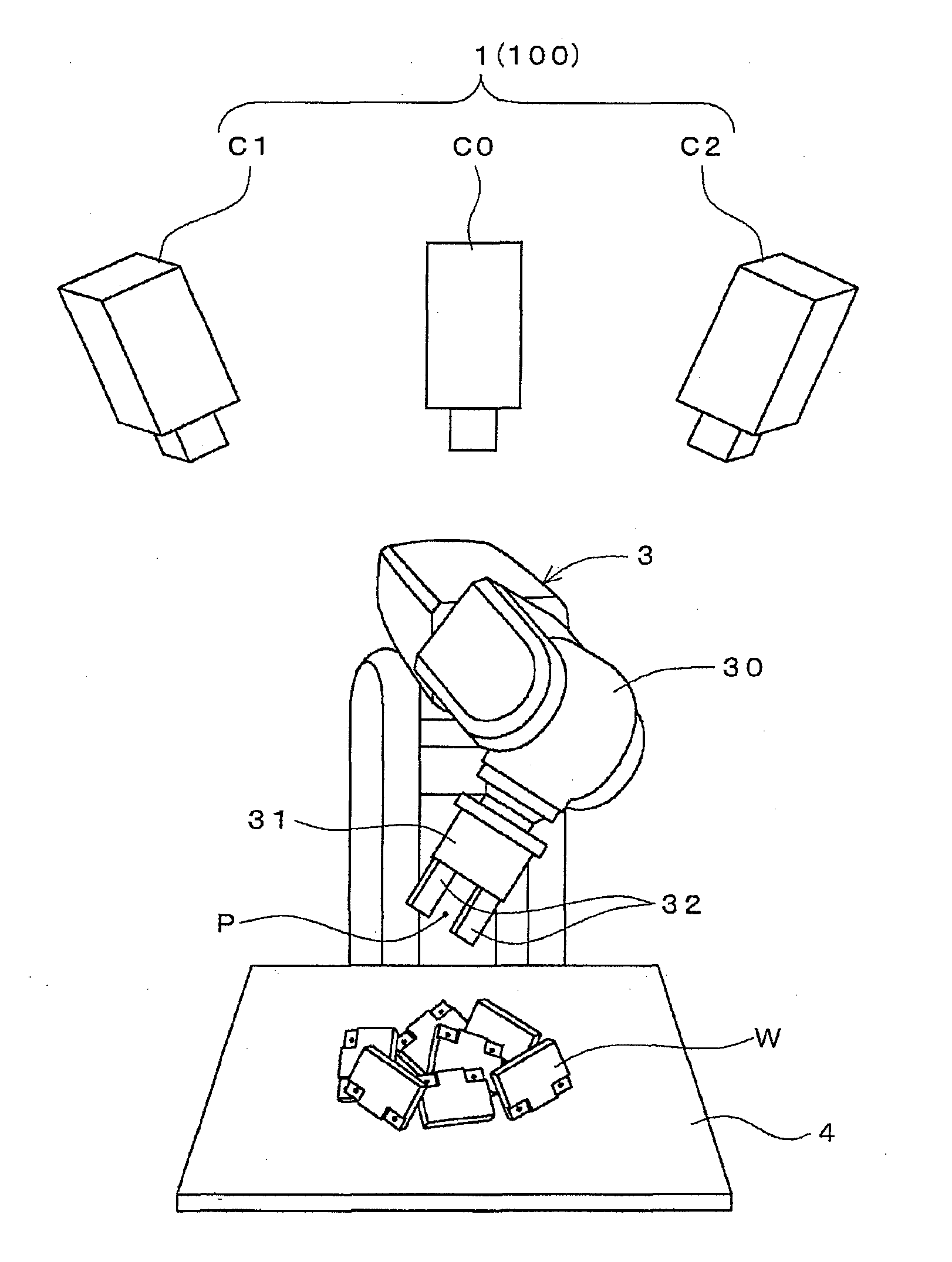
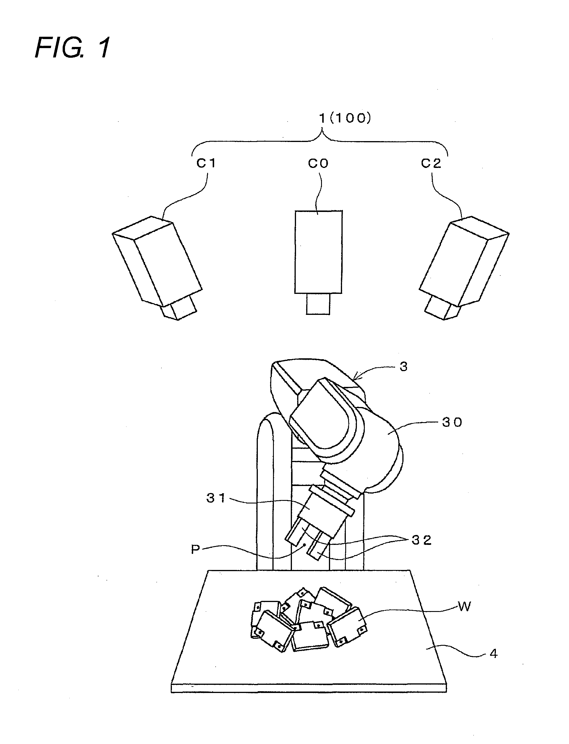
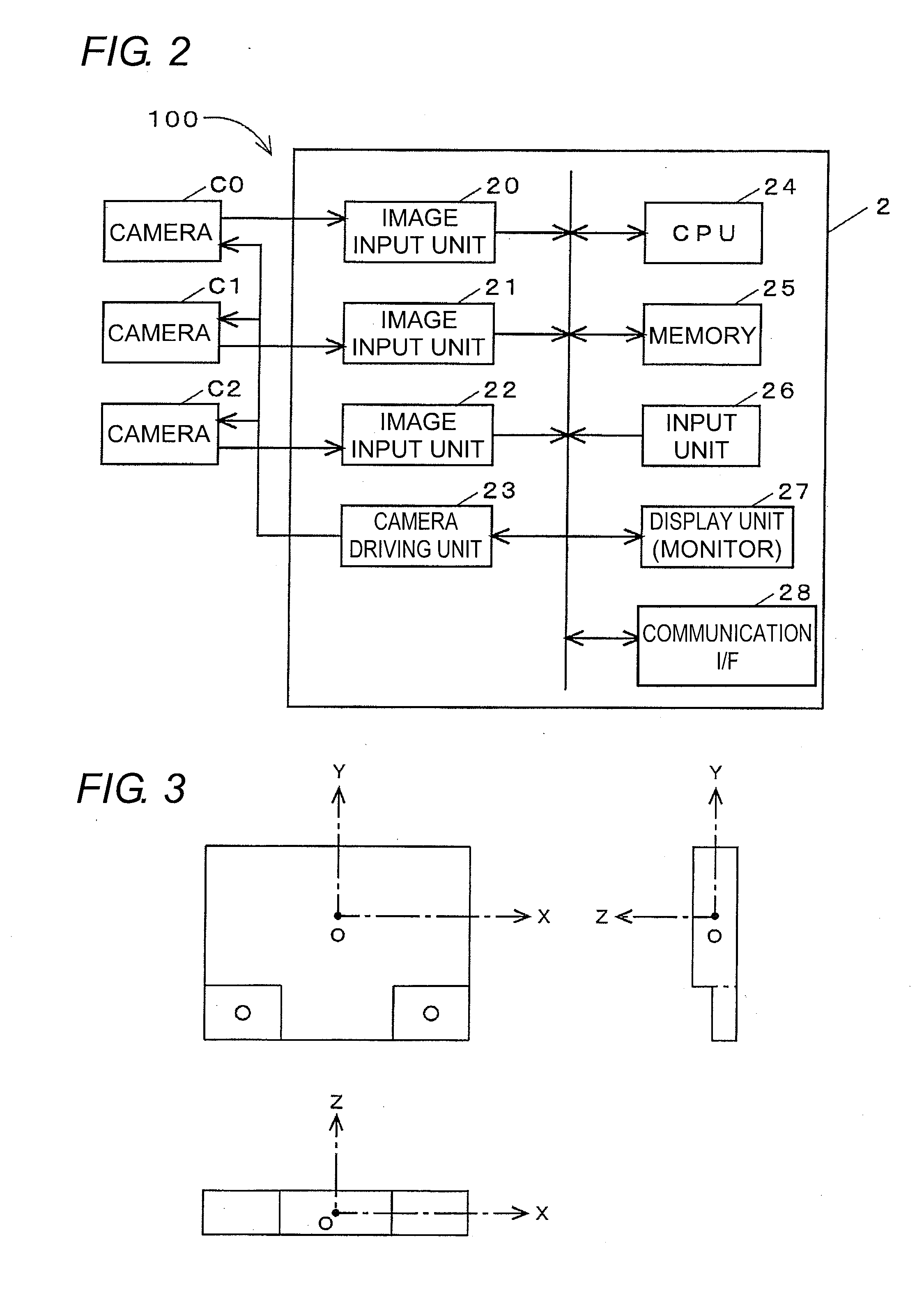
[0027]FIG. 1 shows a picking system to which a three-dimensional visual sensor is introduced, and FIG. 2 shows a configuration of the three-dimensional visual sensor.

[0028]The picking system of this embodiment is used to pick up one by one a workpiece W disrupted on a tray 4 to move the workpiece W to another location. The picking system includes a three-dimensional visual sensor 100 that recognizes the workpiece W, a multijoint robot 3 that performs actual work, and a robot controller (not shown).

[0029]The three-dimensional visual sensor 100 includes a stereo camera 1 and a recognition processing device 2.

[0030]The stereo camera 1 includes three cameras C0, C1, and C2. The central camera C0 is disposed while an optical axis of the camera C0 is oriented toward a vertical direction (that is, the camera C0 takes a front view image), and the right and left cameras C1 and C2 are disposed while optical axes of the cameras C1 and C2 are inclined.

[0031]The recognition processing device 2 i...


PUM


Abstract

A perspective transformation is performed to a three-dimensional model and a model coordinate system indicating a reference attitude of the three-dimensional model to produce a projection image expressing a relationship between the model and the model coordinate system, and a work screen is started up. A coordinate of an origin in the projection image and rotation angles of an X-axis, a Y-axis, and a Z-axis are displayed in work areas on the screen to accept a manipulation to change the coordinate and the rotation angles. The display of the projection image is changed by a manipulation. When an OK button located is pressed, the coordinate and rotation angle are fixed, and the model coordinate system is changed based on the coordinate and rotation angle. A coordinate of each constituent point of the three-dimensional model is transformed into a coordinate of the post-change model coordinate system.

Description

CROSS-REFERENCE TO RELATED PATENT APPLICATIONS[0001]Japan Priority Application 2009-266776, filed Nov. 24, 2009 including the specification, drawings, claims and abstract, is incorporated herein by reference in its entirety.BACKGROUND OF THE INVENTION[0002]1. Technical Field[0003]The present invention relates to a three-dimensional visual sensor that obtains a plurality of three-dimensional coordinates expressing a recognition target by stereo measurement, recognizes a position and an attitude of the recognition target by matching the three-dimensional coordinates with a previously registered three-dimensional model of the recognition target, and outputs the recognition result.[0004]2. Related Art[0005]In a picking system of a factory, the position and attitude of a workpiece to be grasped by a robot are recognized by the stereo measurement, and an arm operation of the robot is controlled based on the recognition result. In order to realize the control, a three-dimensional coordinat...

Claims


Application Information

Patent Timeline
Patent Type & Authority Applications(United States)
IPC IPC(8): H04N13/02H04N13/243
CPCG01B11/03H04N2013/0081H04N13/0242H04N13/0239H04N13/243H04N13/239
Inventor FUJIEDA, SHIROTANENO, ATSUSHITAKAHASHI, REIJIYOSHINO, MASANAOUKAI, KENICHI
Owner ORMON CORP
Why Eureka
Try Eureka