Discrete-time filter apparatus and discrete-time receiver system having the same

a filter and discrete-time receiver technology, applied in the direction of transversal filter, oscillator generator, pulse technique, etc., can solve the problems of large power consumption, difficult to adjust the decimation rate, and insignificant differences between

Inactive Publication Date: 2011-06-23
ELECTRONICS & TELECOMM RES INST
View PDF7 Cites 2 Cited by
  • Summary
  • Abstract
  • Description
  • Claims
  • Application Information

AI Technical Summary

Benefits of technology

[0027]An aspect of the present invention provides a discrete-time filter whose decimation rate can be fr...

Problems solved by technology

The second type of FIR filter structure is disadvantageous in that a great amount of power is consumed due to the presence of an amplifier used for the integrator, and it is difficult to adjust the decimation rate.
The second type of FIR filter structure has better anti-aliasing f...

Method used


Image

  • Discrete-time filter apparatus and discrete-time receiver system having the same
  • Discrete-time filter apparatus and discrete-time receiver system having the same
  • Discrete-time filter apparatus and discrete-time receiver system having the same

Examples


Embodiment Construction

[0043]Exemplary embodiments of the present invention will now be described in detail with reference to the accompanying drawings. The invention may however be embodied in many different forms and should not be construed as limited to the embodiments set forth herein. Rather, these embodiments are provided so that this disclosure will be thorough and complete, and will fully convey the scope of the invention to those skilled in the art.

[0044]In the drawings, the shapes and dimensions may be exaggerated for clarity, and the same reference numerals will be used throughout to designate the same or like components.

[0045]Unless explicitly described to the contrary, the word “comprise” and variations such as “comprises” or “comprising,” will be understood to imply the inclusion of stated elements but not the exclusion of any other elements.

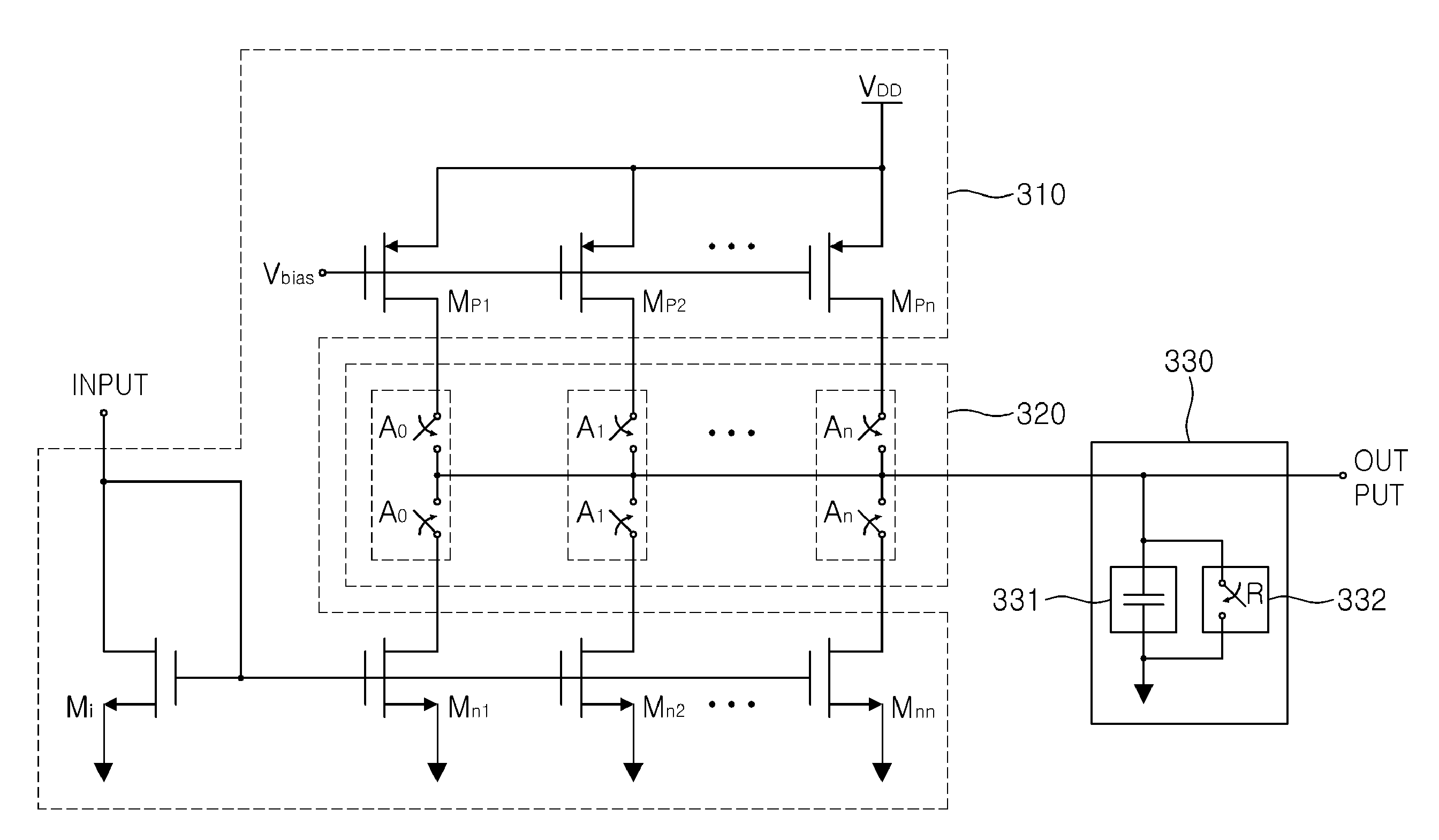
[0046]FIG. 3A is a function block diagram of a discrete-time filter according to an exemplary embodiment of the present invention.

[0047]With reference t...


PUM


Abstract

The discrete-time receiver system includes: a voltage current conversion device low-noise-amplifying an input voltage signal, and converting the amplified signal into a current signal; a first filter performing IIR filtering on the current signal output from the voltage current conversion device; a discrete-time filter performing FIR filtering on a signal output from the first filter; and a second filter performing IIR filtering on a signal output from the discrete-time filter, wherein the discrete-time filter includes a plurality of current supply units generating a current having a size obtained by multiplying an input current by a determined gain, respectively, an adding unit adding currents supplied from the plurality of current supply units, and a plurality of controllers connecting the plurality of current supply units and the adding unit and controlling the flow of current supplied from the current supply units to the adding unit.

Description

CROSS-REFERENCE TO RELATED APPLICATIONS[0001]This application claims the priority of Korean Patent Application Nos. 10-2009-0127485 filed on Dec. 18, 2009 and 10-2010-0114424 filed on Nov. 17, 2010, in the Korean Intellectual Property Office, the disclosures of which are incorporated herein by reference.BACKGROUND OF THE INVENTION[0002]1. Field of the Invention[0003]The present invention relates to a discrete-time filter and, more particularly, to a discrete-time filter using a switch and a capacitor in a semiconductor circuit field.[0004]2. Description of the Related Art[0005]A digital radio frequency (RF) technique is based on a discrete-time signal processing scheme which may be able to fully utilize a high speed switching operation of accurate timing, one of the merits of a complementary metal oxide semiconductor (CMOS) process. Also, in the digital RF technique, a basic philosophy allows for rapidly developed corresponding designs when a process adopted for a design is shifted ...

Claims


Application Information

Patent Timeline
IPC IPC(8): H03K5/00
CPCH03H15/00
Inventor LEE, YOUNG JAE
Owner ELECTRONICS & TELECOMM RES INST
Why Eureka
Try Eureka