Al technical title is built by PatSnap Al team. It summarizes the technical point description of the patent document.
a joint arthrodesis and joint technology, applied in the field of surgical implants, can solve the problems of lack of adequate compression, complicated cannulated screws, and problems with the current system for ankle arthrodesis and arthroplasty
Active Publication Date: 2011-07-07
MEDICINELODGE +1
View PDF43 Cites 92 Cited by
Summary
Abstract
Description
Claims
Application Information
AI Technical Summary
This helps you quickly interpret patents by identifying the three key elements:
Problems solved by technology
Method used
Benefits of technology
Problems solved by technology
However, problems exist with some of the current systems for ankle arthrodesis and arthroplasty.
First, some cannulated screws have been complicated by hardware failure prior to complete fusion, as well as lack of adequate compression across the fusion site.
Depending on the orientation of screw insertion, the screws may not restrict motion in the plane of motion of the joint and therefore increase the likelihood of development of nonunion.
Second, some plate systems are often able to accommodate deformity in only one plane, and also can cause prominence that leads to postoperative skin irritation.
Current retrograde fusion nails are not designed to specifically fuse the posterior facet of the subtalar joint.
A common complication of current retrograde systems involves a nonunion of the posterior facet joint because they do not specifically fuse this area with the fusion nail.
The plantar skin incision that is required for the retrograde nail has been associated with wound complications and injury to the plantar branch of the tibia...
Method used
Image
Click on the blue label to locate the original text in one second.
Reading with bidirectional positioning of images and text.
Examples
Embodiment Construction
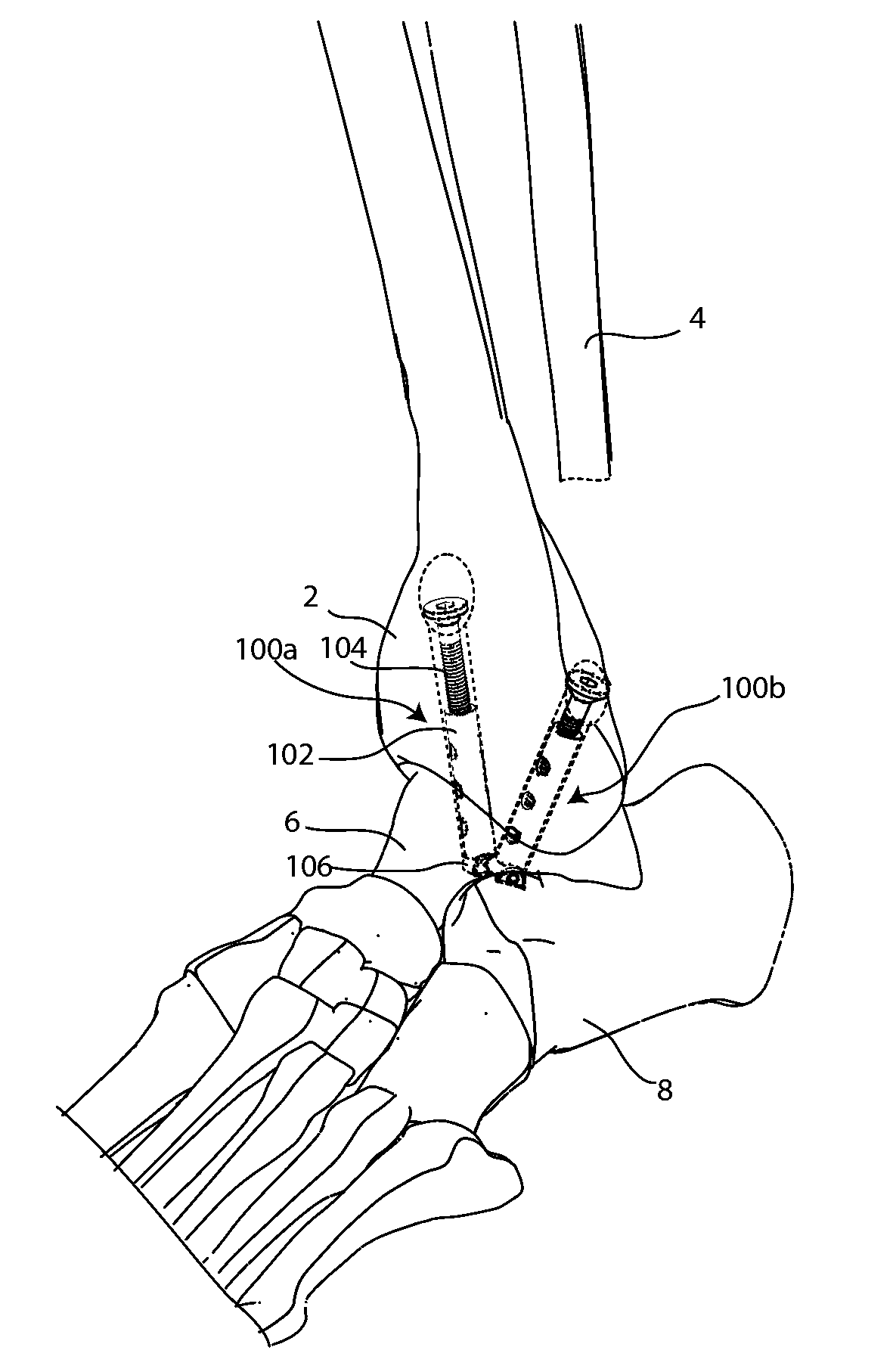
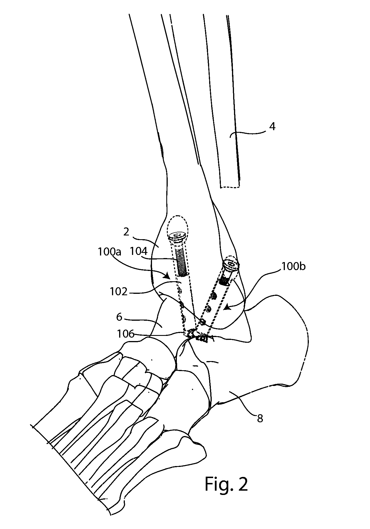
[0054]The present invention relates to implants for ankle arthrodesis and / or arthroplasty. Those of skill in the art will recognize that the following description is merely illustrative of the principles of the invention, which may be applied in various ways to provide many different alternative embodiments. This description is made for the purpose of illustrating the general principles of this invention and is not meant to limit the inventive concepts in the appended claims.
[0055]One embodiment of the invention may be an implantable bone fixation system for providing compression between a first exterior bone surface and a second exterior bone surface. The bone fixation system may include a first elongated structure, a second elongated structure, and an anchor. The first elongated structure may have a head and a shaft, the head shaped to bear against the first exterior bone surface. The second elongated structure may have a proximal end, a distal end, a longitudinal axis extending b...
PUM
Abstract
An implantable fixation system for fusing a joint between a first bone and a second bone. The system may include an anchor, standoff, bolt, and cortical washer. The system may be implanted across the joint along a single trajectory, the length of the system adjustable to provide compressive force between the anchor and the cortical washer. The system may be implanted across a tibiotalar joint with the anchor positioned in the sinus tarsi. A spacing member may be inserted between the two bones and the fixation system implanted to extend through an opening in the spacing member. The spacing member may be anatomically shaped and/or provide deformity correction. An ankle arthroplasty system may include a tibial plate, a talar plate, and a bearing insert. The plates may be anchored to the tibia and talus along a single trajectory. The ankle arthroplasty system may be revisable to a fusion system.
Description
CROSS-REFERENCE TO RELATED APPLICATIONS[0001]This application claims the benefit of the following:[0002]pending U.S. Provisional Patent Application No. 61 / 225,398, filed Jul. 14, 2009, which carries Applicants' docket no. NND-1 PROV, and is entitled MODULAR ANKLE HEMIARTHROPLASTY;[0003]pending U.S. Provisional Patent Application No. 61 / 254,500, filed Oct. 23, 2009, which carries Applicants' docket no. DUG-6 PROV, and is entitled SYSTEMS AND METHODS FOR ANKLE REPLACEMENT, ANKLE FUSION AND HINDFOOT FUSION;[0004]pending U.S. Provisional Patent Application No. 61 / 254,512, filed Oct. 23, 2009, which carries Applicants' docket no. DUG-7 PROV, and is entitled SYSTEMS AND METHODS FOR WRIST ARTHROPLASTY AND WRIST FUSION;[0005]pending U.S. Provisional Patent Application No. 61 / 323,156, filed Apr. 12, 2010, which carries Applicants' docket no. DUG-8 PROV, and is entitled ANKLE INTRAMEDULLARY ARTHRODESIS AND ARTHOPLASTY SYSTEM;[0006]pending U.S. Provisional Patent Application No. 61 / 323,170, fi...
Claims
Application Information
Patent Timeline
Application Date:The date an application was filed.
Publication Date:The date a patent or application was officially published.
First Publication Date:The earliest publication date of a patent with the same application number.
Issue Date:Publication date of the patent grant document.
PCT Entry Date:The Entry date of PCT National Phase.
Estimated Expiry Date:The statutory expiry date of a patent right according to the Patent Law, and it is the longest term of protection that the patent right can achieve without the termination of the patent right due to other reasons(Term extension factor has been taken into account ).
Invalid Date:Actual expiry date is based on effective date or publication date of legal transaction data of invalid patent.