Light emitting device, and illumination light source, display unit and electronic apparatus including the light emitting device

Inactive Publication Date: 2011-09-01
PANASONIC CORP
View PDF14 Cites 30 Cited by
  • Summary
  • Abstract
  • Description
  • Claims
  • Application Information

AI Technical Summary

Benefits of technology

[0019]The present invention can provide a three-band white light emitting device in which the color tone is controlled easily. Moreover, the present invention can provide an illumination light source, particularly a backlight, configured so that the unevennesses of color and brightness

Problems solved by technology

(1) Since the photon conversion efficiency from the blue light irradiating the green phosphor to the green light is low, the use amount of the green phosphor increases, leading to high cost.
(2) Since, in general, the green phosphor has a sharp absorption property with respect to the wavelength of the blue light, the spectral distribution of the bluish green light tends to vary easily due to a slight property difference between the blue LED and the green phosphor.
(3) The green light having an emission spectrum with a wide half value width is used because the choice of the green phosphor is limited. Thus, the light component ratios of the bluish green and yellow in the output light increase and the color

Method used


Image

  • Light emitting device, and illumination light source, display unit and electronic apparatus including the light emitting device
  • Light emitting device, and illumination light source, display unit and electronic apparatus including the light emitting device
  • Light emitting device, and illumination light source, display unit and electronic apparatus including the light emitting device

Examples


embodiment 1

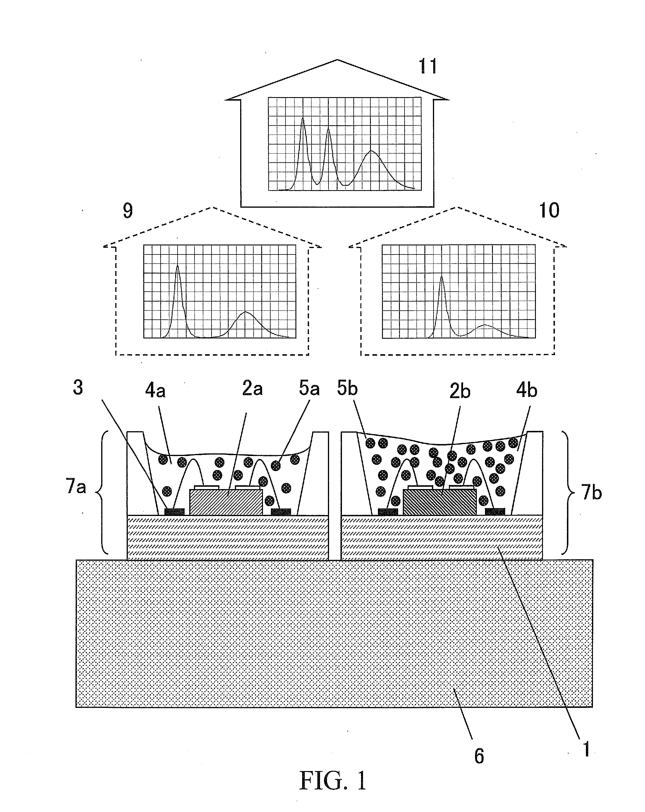
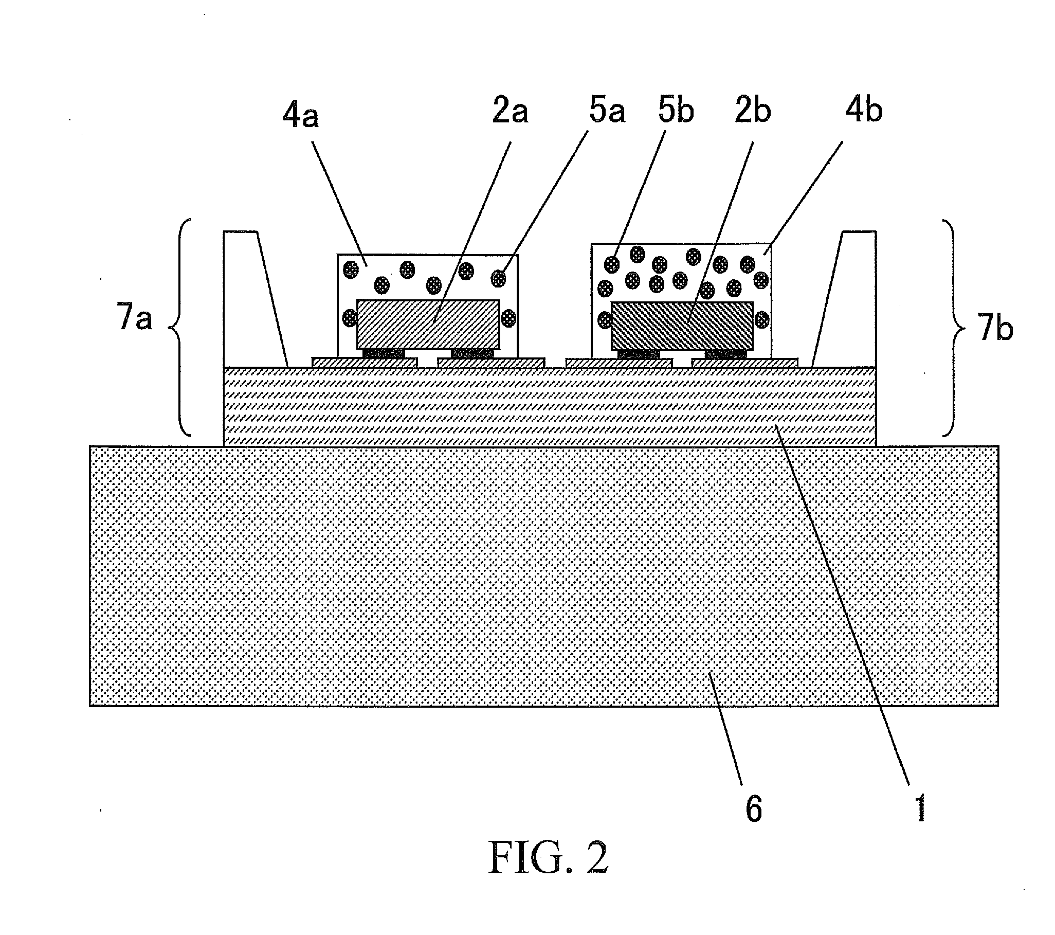
[0028]FIGS. 1 and 2 each are a diagram showing an example of Embodiment 1 that is a light emitting device according to the present invention.

[0029]The light emitting device of Embodiment 1 includes: a first semiconductor light emitting element 7a having a solid-state blue light emitting element 2a that emits blue light with a light emission peak in a wavelength range from 420 nm to less than 480 nm, and a first red phosphor layer 4a that covers the solid-state blue light emitting element 2a and includes a first red phosphor 5a that emits red light with a light emission peak in a wavelength range from 600 nm to less than 680 nm; and a second semiconductor light emitting element 7b having a solid-state green light emitting element 2b that emits green light with a light emission peak in a wavelength range from 500 nm to less than 550 nm, and a second red phosphor layer 4b that covers the solid-state green light emitting element 2b and includes a second red phosphor 5b that emits red li...

embodiment 2

[0065]Next, an embodiment of the illumination light source according to the present invention will be described.

[0066]By using the light emitting device of Embodiment 1, it is possible to fabricate an illumination light source, such as a light source for an illumination apparatus including an illumination lamp and a thin illumination apparatus, and a light source (backlight) for an image display unit, in accordance with a publicly known method.

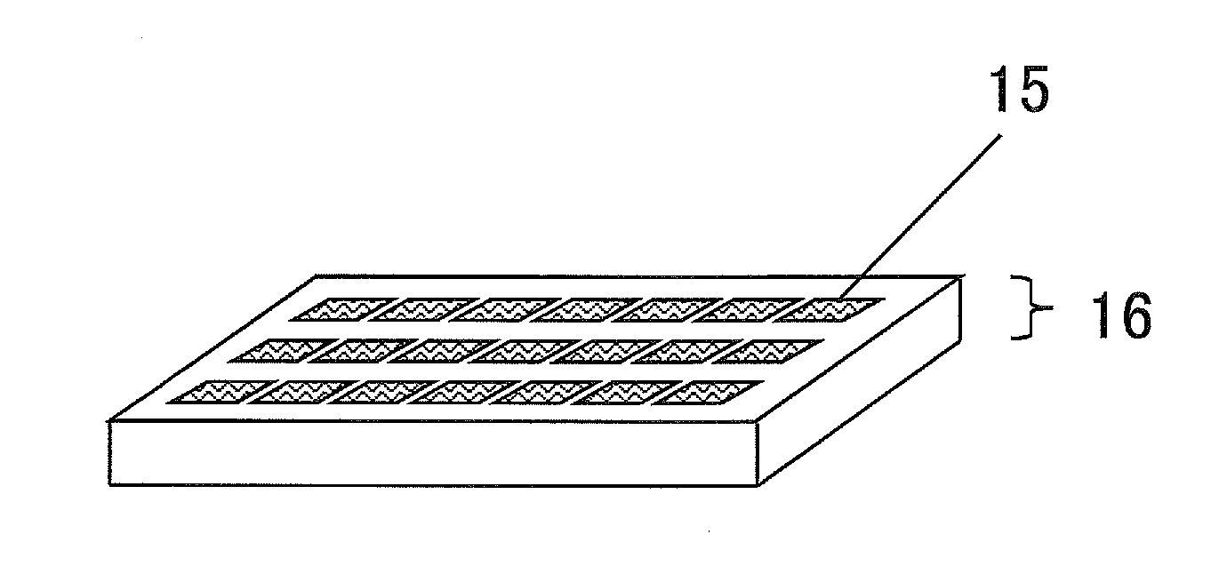
[0067]FIG. 7 is a schematic perspective view showing an example of a backlight as one specific example of the illumination light source according to the present invention. In a backlight 16, a plurality of the light emitting devices of Embodiment 1 are disposed dispersedly. The backlight 16 utilizes, as light emitted from a light emitting part 15, the output light 11 emitted from the light emitting device of Embodiment 1, or the purplish mixed color light 9 emitted from the first semiconductor light emitting element 7a and the yellowish mixed ...

embodiment 3

[0069]Next, an embodiment of the display unit according to the present invention will be described.

[0070]The display unit of Embodiment 3 includes the backlight of Embodiment 2 and can be fabricated using the backlight of embodiment 2 in accordance with a publicly known method. A typical example of the display unit is an LCD (liquid crystal display panel), which can be fabricated using at least the backlight of Embodiment 2, a light modulation element, and a color filter in combination.

[0071]The display unit according to the present invention is configured so that the unevennesses of color and brightness are suppressed, no lot-to-lot variation occurs during production, and the product yield is increased. Moreover, the color purities of RGB in the output light are satisfactory, the wide color gamut display is possible, and high contrast and high brightness images can be displayed.


PUM


Abstract

A light emitting device includes: a first semiconductor light emitting element having a solid-state blue light emitting element that emits blue light with a light emission peak in a wavelength range from 420 nm to less than 480 nm, and a first red phosphor layer that covers the solid-state blue light emitting element and includes a first red phosphor that emits red light with a light emission peak in a wavelength range from 600 nm to less than 680 nm; and a second semiconductor light emitting element having a solid-state green light emitting element that emits green light with a light emission peak in a wavelength range from 500 nm to less than 550 nm, and a second red phosphor layer that covers the solid-state green light emitting element and includes a second red phosphor that emits red light with a light emission peak in a wavelength range from 600 nm to less than 680 nm.

Description

BACKGROUND OF THE INVENTION[0001]1. Field of the Invention[0002]The present invention relates to a light emitting device utilizing solid-state light emitting elements and phosphors. The present invention also relates to an illumination light source, such as a backlight, including the light emitting device, and further relates to a display unit including the backlight and to an electronic apparatus including the display unit.[0003]2. Description of Related Art[0004]Conventionally, a light emitting device including a solid-state light emitting element, such as a light emitting diode (hereinafter referred to as an LED), and a phosphor in combination has been used as a light emitting device (hereinafter referred to as a three-band white light emitting device) that emits three-band white light usable as illumination light or backlight for a display unit.[0005]Such a light emitting device has a configuration in which the solid-state light emitting element is covered with a phosphor layer....

Claims


Application Information

Patent Timeline
IPC IPC(8): G02F1/13357H01L33/44
CPCF21K9/00H01L25/0753H01L33/50H01L33/54G02F1/133611G02F2001/133624G02F2001/133614G02F1/133603G02F1/133609H01L2224/48091H01L2924/00014G02F1/133624G02F1/133614
Inventor OSHIO, SHOZO
Owner PANASONIC CORP
Why Eureka
Try Eureka