Semiconductor integrated circuit and disk recording and reproducing drive using the same

a technology of integrated circuits and disks, applied in the direction of digital recording, recording signal processing, instruments, etc., can solve the problems that the internal signal and the disk read data cannot be measured by the external detection device, and achieve the effect of reducing time and effort and suppressing a change in the characteristi

Inactive Publication Date: 2011-09-01
RENESAS ELECTRONICS CORP
View PDF4 Cites 3 Cited by
  • Summary
  • Abstract
  • Description
  • Claims
  • Application Information

AI Technical Summary

Benefits of technology

[0008]Prior to the present invention, the present inventors have been engaged in the research/development of a semiconductor integrated circuit mounted to an optical disk recording and reproducing drive that records/reproduces information about an optical disk such as a CD, a DVD, a BD or the like. In the process of this research/development, the present inventors have carried out a study about the technology described in the patent document 2 prior to the ...

Problems solved by technology

In this technology, however, the problem that the disk read data and the internal signal of the servo controller cann...

Method used


Image

  • Semiconductor integrated circuit and disk recording and reproducing drive using the same
  • Semiconductor integrated circuit and disk recording and reproducing drive using the same
  • Semiconductor integrated circuit and disk recording and reproducing drive using the same

Examples


first embodiment

Configuration of Optical Disk Recording and Reproducing Drive

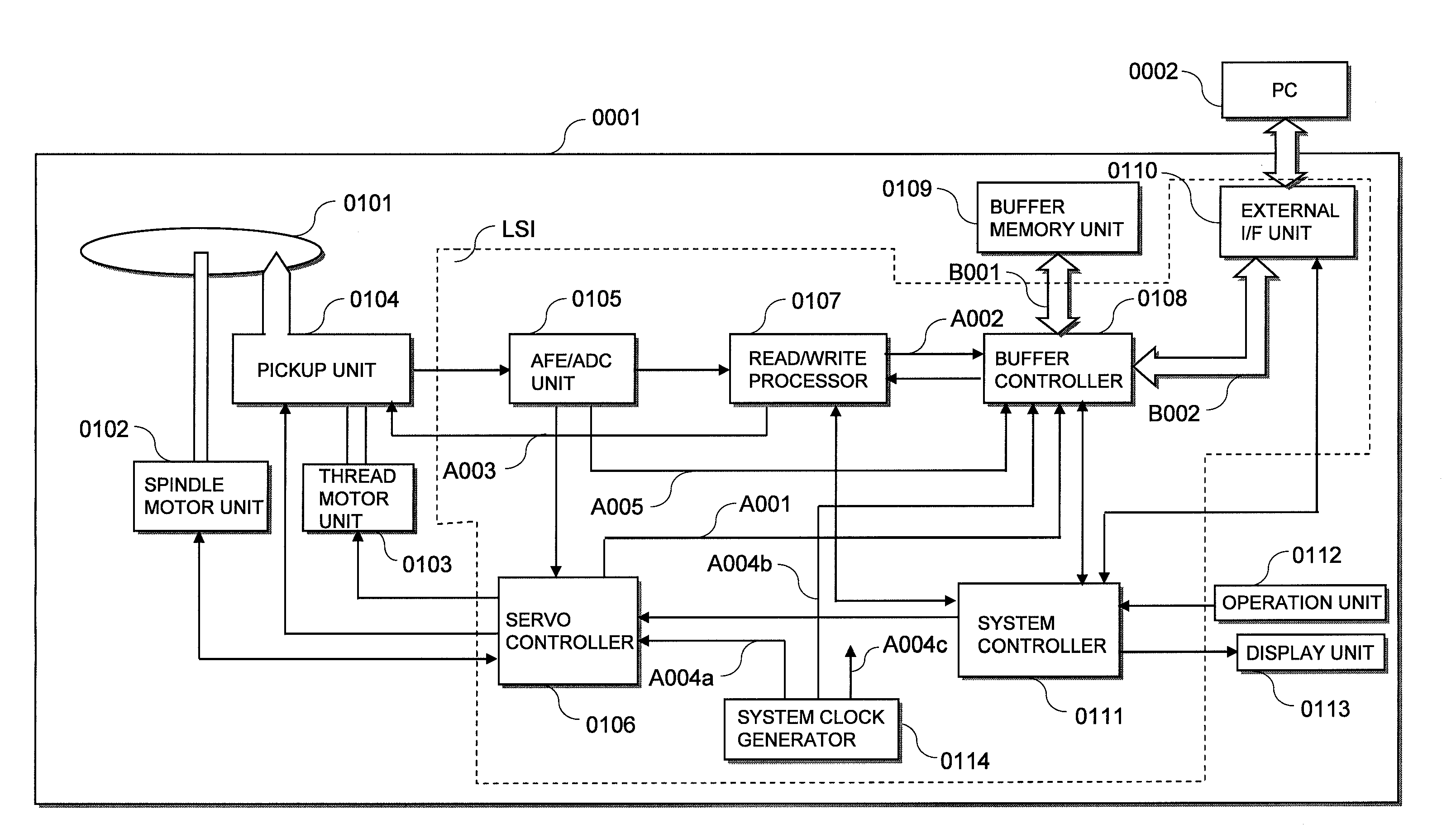
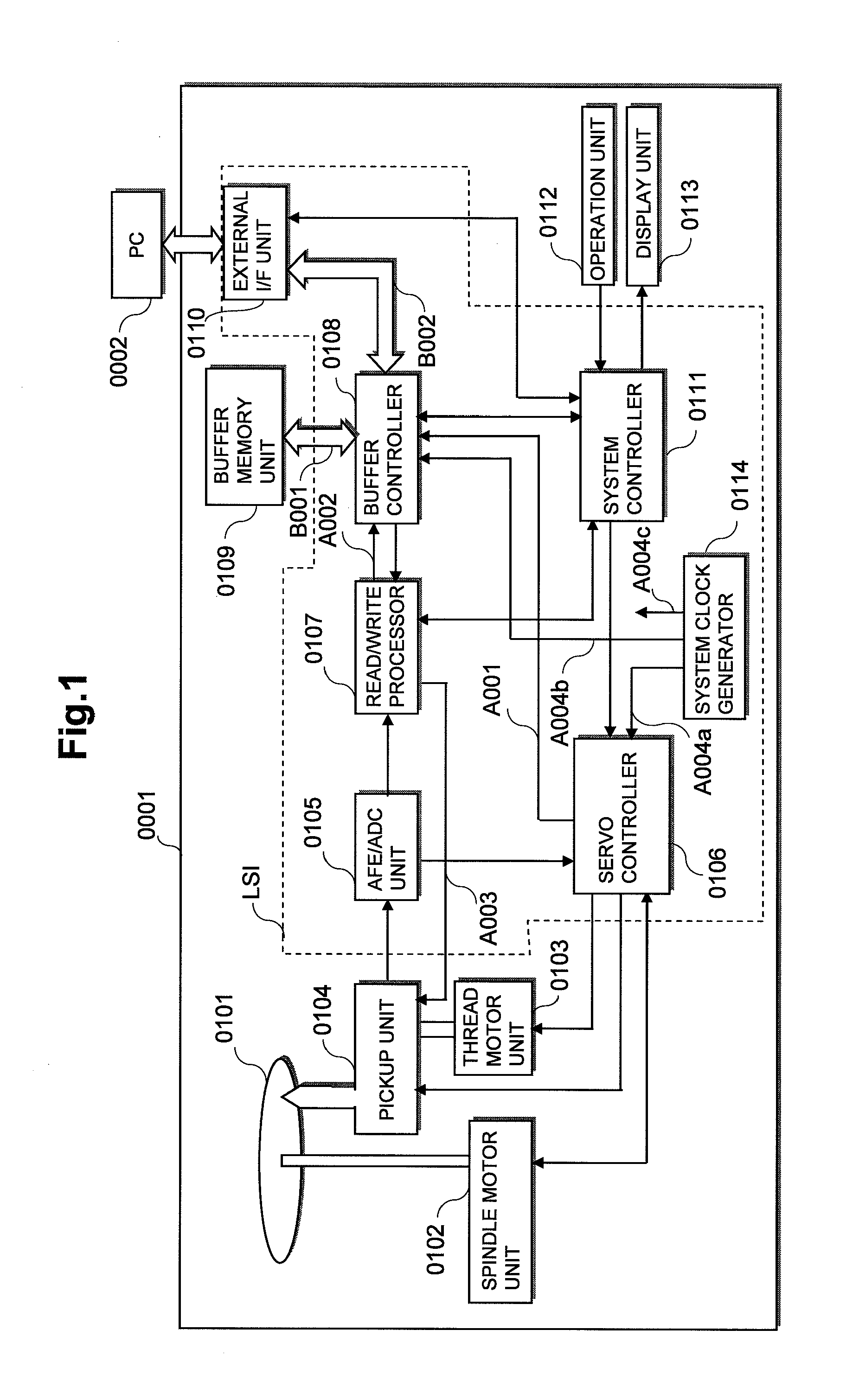
[0072]FIG. 1 is a diagram showing a configuration of an optical disk recording and reproducing drive according to a first embodiment of the present invention.

[0073]In FIG. 1, the optical disk drive 0001 is coupled to a personal computer (hereinafter called “PC”) 0002.

[0074]The optical disk drive 0001 includes an optical disk 0101, a spindle motor unit 0102, a thread motor unit 0103, a pickup unit 0104, an analog front end / analog to digital converter unit (hereinafter called “AFE / ADC unit”) 0105, a servo controller 0106, a read / write processor 0107, a buffer controller 0108, a buffer memory unit 0109, an external interface unit (hereinafter called “external I / F unit”) 0110, a system controller 0111, an operation unit 0112, a display unit 0113, and a system clock generator 0114. Incidentally, the AFE / ADC unit 0105, servo controller 0106, read / write processor 0107, buffer controller 0108, system controller 0111 and system clo...

second embodiment

Configuration of Optical Disk Recording and Reproducing Drive

[0175]FIG. 13 is a diagram showing a configuration of an optical disk recording and reproducing drive according to a second embodiment of the present invention.

[0176]The optical disk recording and reproducing drive according to the second embodiment of the present invention shown in FIG. 13 is different from the optical disk drive according to the first embodiment of the present invention shown in FIGS. 1 through 12 in that a trigger controller 0306 is added to a memory access controller 0304 of a buffer controller 0108 shown in FIG. 13.

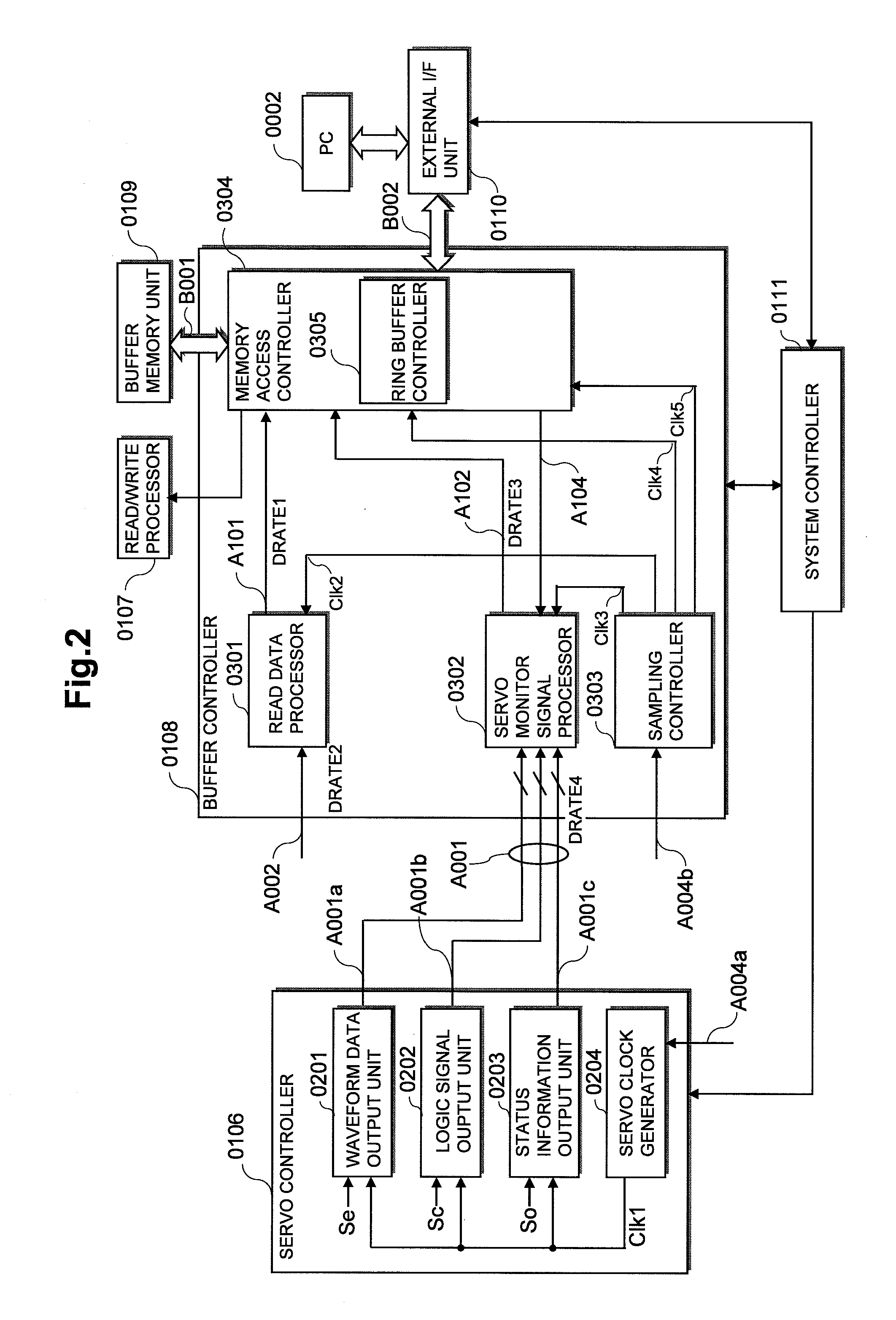
[0177]The trigger controller 0306 of the buffer controller 0108 shown in FIG. 13 performs a trigger determining process on a processed servo monitor signal A102 supplied from a servo monitor signal processor 0302 to the memory access controller 0304, based on settings from a system controller 0111. This trigger determining process will be explained in detail later.

[0178]When the trigger con...

third embodiment

Configuration of Optical Disk Recording and Reproducing Drive

[0231]FIG. 29 is a diagram showing a configuration of an optical disk recording and reproducing drive according to a third embodiment of the present invention.

[0232]The optical disk recording and reproducing drive according to the third embodiment of the present invention shown in FIG. 29 is different from the optical disk drive according to the first embodiment of the present invention shown in FIGS. 1 through 12 in that an AFE / ADC unit 0105 shown in FIG. 29 has the function of outputting an RF signal generated and digitized inside the AFE / ADC unit 0105 to a buffer controller 0108 as an RF monitor signal A005 in such a manner as to be able to observe the RF signal outside the optical disk drive 0001.

[0233]According to the optical disk drive 0001 of the third embodiment of the present invention shown in FIG. 29, the RF monitor signal A005 can also be stored in a buffer memory unit 0109 in addition to a servo monitor signal...


PUM


Abstract

The present invention enables a comprehensive evaluation from both of data read from a disk and a servo signal of a servo controller. The present invention provides a semiconductor integrated circuit mountable to a disk recording and reproducing drive, which comprises a signal processor of an RF signal read from a pickup, a servo controller responsive to a servo error signal read from the pickup, a memory controller, and an external interface. The memory controller is supplied with read data and a servo signal and stores the read data and the servo signal in a buffer memory according to a time division process. The read data and the servo signal stored in the buffer memory can be transferred to an external device via the external interface by the memory controller.

Description

CLAIM OF PRIORITY[0001]The present application claims priority from Japanese application JP 2010-042589 filed on Feb. 26, 2010, the content of which is hereby incorporated by reference into this application.FIELD OF THE INVENTION[0002]The present invention relates to a semiconductor integrated circuit and a disk recording and reproducing drive using the same, and in particular to a technology effective in enabling a comprehensive evaluation from both data read from a disk and an internal signal of a servo controller.BACKGROUND OF THE INVENTION[0003]In an optical disk recording and reproducing drive which records / reproduces information of optical disks such as a CD (Compact Disk), a DVD (Digital Versatile Disk), a BD (Blu-Ray Disk), etc., laser light emitted from an optical pickup is applied onto an optical disk recording surface and its reflected light is detected by the optical pickup, so that an RF analog reproduction signal is generated. The recording and reproduction of such an ...

Claims


Application Information

Patent Timeline
IPC IPC(8): G11B7/00
CPCG11B19/048
Inventor NAKANO, NORIHIKOISHIHARA, HAJIMEFUKUSHIMA, AKIO
Owner RENESAS ELECTRONICS CORP
Why Eureka
Try Eureka