Method for transmitting data in multiple antenna system

a data transmission and antenna system technology, applied in the field of wireless communications, to achieve the effect of further flexible allocation of radio resources

Active Publication Date: 2011-09-01
LG ELECTRONICS INC
View PDF8 Cites 6 Cited by
  • Summary
  • Abstract
  • Description
  • Claims
  • Application Information

AI Technical Summary

Benefits of technology

[0012]According to the present invention, effective data decoding is possible regardless of whether radio resources to be allocated to multiple users are partially or entirely paired. Therefore, the radio resources can be further flexibly allocated to the users.

Problems solved by technology

In a region where the radio resources are paired, data of other users acts as interference to data of a current user.

Method used


Image

  • Method for transmitting data in multiple antenna system
  • Method for transmitting data in multiple antenna system
  • Method for transmitting data in multiple antenna system

Examples


Embodiment Construction

[0021]Hereinafter, exemplary embodiments of the present invention will be described in detail with reference to the accompanying drawings.

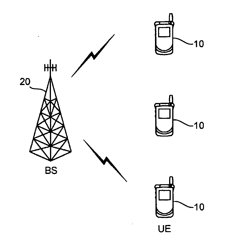
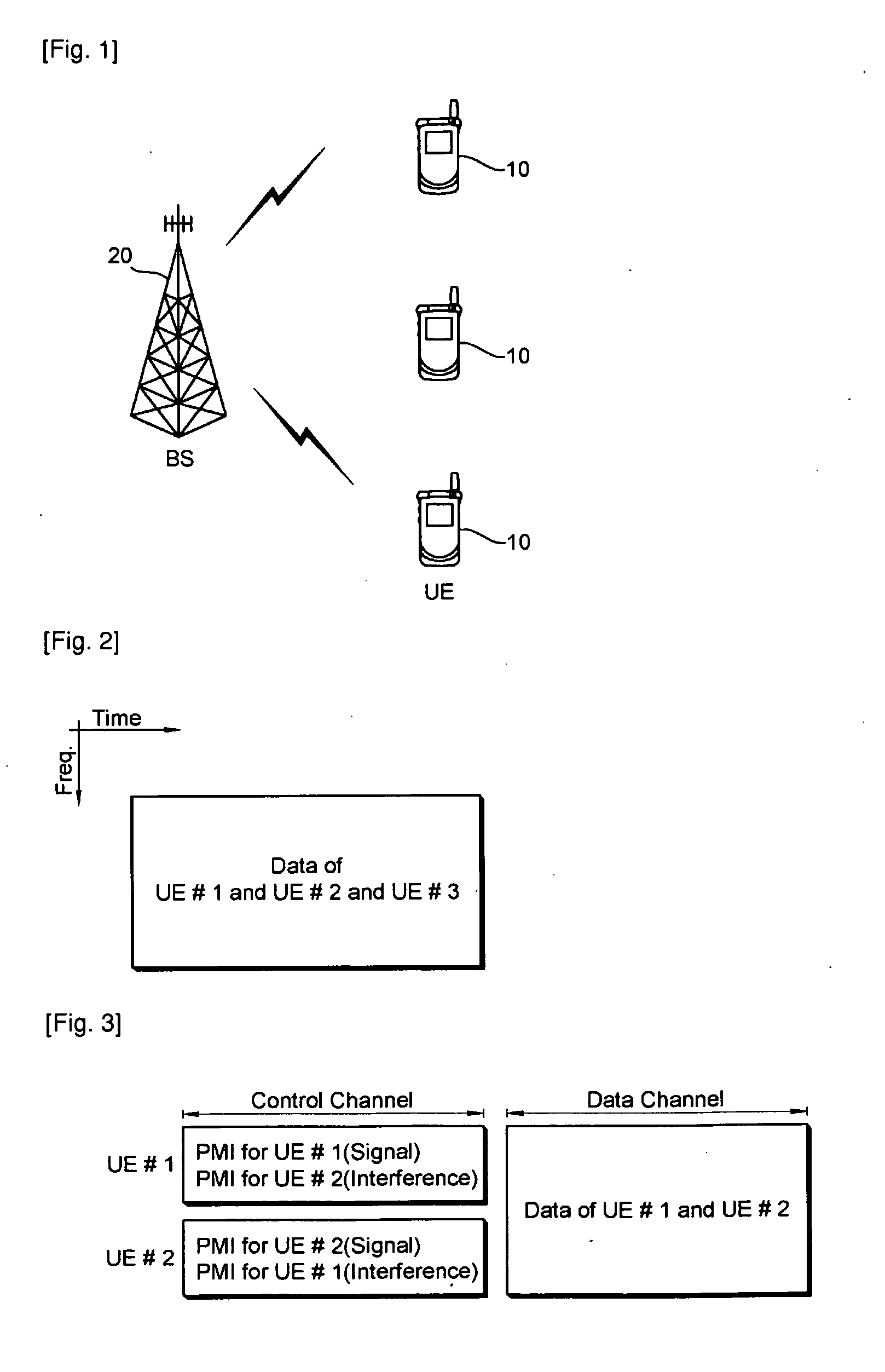
[0022]FIG. 1 shows a wireless communication system. The wireless communication system can be widely deployed to provide a variety of communication services, such as voices, packet data, etc.

[0023]Referring to FIG. 1, the wireless communication system includes at least one user equipment (UE) 10 and a base station (BS) 20. The UE 10 may be fixed or mobile, and may be referred to as another terminology, such as a mobile station (MS), a user terminal (UT), a subscriber station (SS), a wireless device, etc. The BS 20 is generally a fixed station that communicates with the UE 10 and may be referred to as another terminology, such as a node-B, a base transceiver system (BTS), an access point, etc. There are one or more cells within the coverage of the BS 20.

[0024]Hereinafter, a downlink is defined as a communication link from the BS 20 to the UE 10, and...


PUM


Abstract

A method of transmitting data in a multiple antenna system includes transmitting a precoding matrix index (PMI) of a first user through a control channel for the first user, and transmitting the PMI of the first user and a PMI of a second user through a data channel for the first user. Effective data decoding is possible regardless of whether radio resources to be allocated to multiple users are partially or entirely allocated to the users.

Description

TECHNICAL FIELD[0001]The present invention relates to wireless communications, and more particularly, to a data transmission method capable of effectively transmitting and decoding data of multiple users in a multiple antenna system.BACKGROUND ART[0002]Recently, to maximize performance and communication capability of wireless communication systems, attention is paid to a multiple input multiple output (MIMO) system. Being evolved from the conventional technique in which a single transmit (Tx) antenna and a single receive (Rx) antenna are used, a MIMO technique uses multiple Tx antennas and multiple Rx antennas in order to improve efficiency of data transmission and reception. The MIMO system is also referred to as a multiple antenna system. In the MIMO technique, instead of receiving one whole message through a single antenna path, data segments are received through a plurality of antennas and are then assembled into one piece of data. As a result, a data transfer rate can be improv...

Claims


Application Information

Patent Timeline
Patent Type & Authority Applications(United States)
IPC IPC(8): H04W72/04H04L25/49H04W4/00
CPCH04B7/0665H04B7/0452H04B7/06H04L5/00
Inventor KO, HYUN SOOIHM, BIN CHULCHUN, JIN YOUNGLEE, MOON IL
Owner LG ELECTRONICS INC
Why Eureka
Try Eureka