Power headroom reporting method and device and computer storage medium

A technology of power headroom and power control parameters, applied in the field of wireless communication, can solve problems such as inability to obtain power headroom information and inability to reasonably schedule BWP uplink signal transmission

Active Publication Date: 2020-08-14
GUANGDONG OPPO MOBILE TELECOMM CORP LTD
View PDF9 Cites 0 Cited by
  • Summary
  • Abstract
  • Description
  • Claims
  • Application Information

AI Technical Summary

Problems solved by technology

At present, each carrier has only one PHR, and the network side cannot obtain specific power headroom information on each BWP in the carrier, so it is impossible to reasonably schedule the uplink signal transmission on each BWP

Method used


Image

  • Power headroom reporting method and device and computer storage medium
  • Power headroom reporting method and device and computer storage medium
  • Power headroom reporting method and device and computer storage medium

Examples


example 1

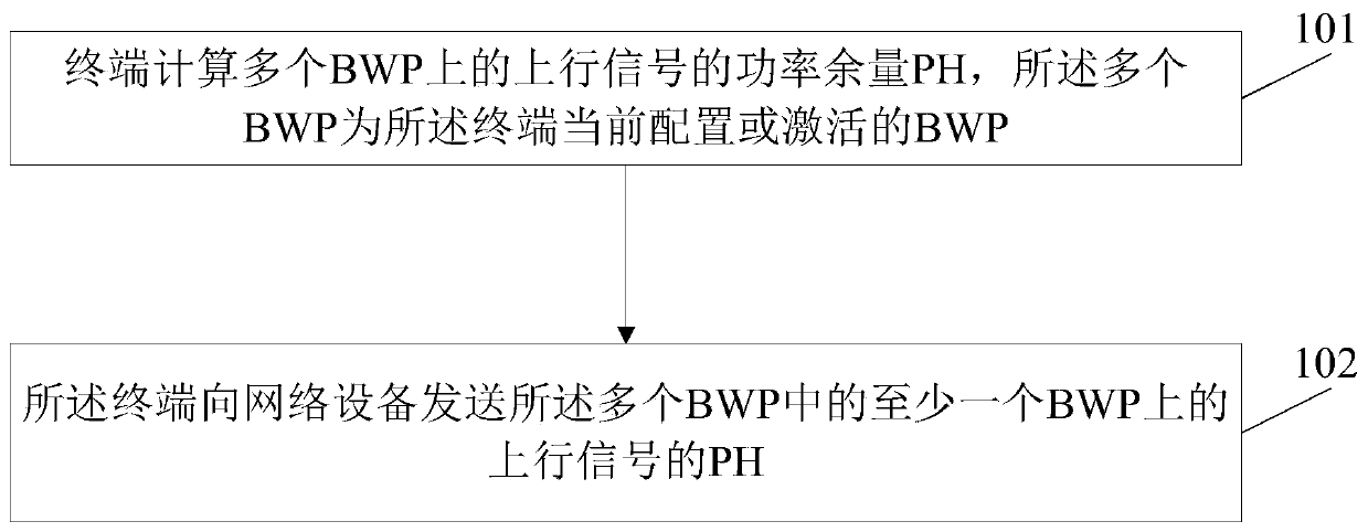
[0120] Example 1: The method for the terminal to calculate the real PH of the PUSCH on the BWP k based on the transmission parameters and power control parameters of the PUSCH on the BWP k on the carrier c is as follows:

[0121]

[0122] The parameters in the above formula are parameters configured or indicated for the PUSCH on the BWP k (that is, parameters specific to each BWP), wherein, Indicates the transmission bandwidth of PUSCH, Δ TF,f,c,k (i) According to the modulation and coding method, μ is the subcarrier spacing of PUSCH transmission, P CMAX,f,c,k (i) is the maximum transmit power of the terminal on the BWP, P O_PUSCH,f,c,k (j) is the PUSCH target received power, α f,c,k (j) is the path loss factor, PL f,c,k (q d ) is the estimated value of path loss, f f,c,k (i, l) is the closed-loop power adjustment factor.

example 2

[0123] Example 2: The method for the terminal to calculate the virtual PH of the PUSCH on the BWP k based on the power control parameters of the PUSCH on the BWP k on the carrier c is as follows:

[0124]

[0125] The parameters in the above formula are power control parameters configured or indicated for the PUSCH on the BWP k (that is, parameters specific to each BWP), where, is the maximum transmit power assumed by the terminal on the BWP, P O_PUSCH,f,c,k (j) is the PUSCH target received power, α f,c,k (j) is the path loss factor, PL f,c,k (q d ) is the estimated value of path loss, f f,c,k (i, l) is the closed-loop power adjustment factor.

example 3

[0126] Example 3: The method for the terminal to calculate the real PH of the SRS on the BWP k based on the transmission parameters and power control parameters of the SRS on the BWP k on the carrier c is as follows:

[0127] pH type3,f,c,k (i,q s ,l)=

[0128] P CMAX,f,c,k (i)-{P O_SRS,f,c,k (q s )+10log 10 (2 μ M SRS,f,c,k (i))+α SRS,f,c,k (q s )·PL f,c,k (q s )+h f,c,k (i,l)}

[0129] The parameters in the above formula are parameters configured or indicated for the SRS on the BWP k (that is, parameters specific to each BWP), where M SRS,f,c,k (i) represents the SRS transmission bandwidth, μ is the subcarrier spacing of SRS transmission, P CMAX,f,c,k (i) is the maximum transmit power of the terminal on the BWP, P O_SRS,f,c,k (q s ) is the target received power, α SRS,f,c,k (q s ) is the path loss factor, PL f,c,k (q s ) is the estimated value of path loss, h f,c,k (i,l) is the SRS closed-loop power adjustment factor.


PUM


Abstract

The invention discloses a power headroom reporting method and device and a computer storage medium, and the method comprises the steps that a terminal calculates the power headroom PH of uplink signals on a plurality of bandwidth parts BWPs, and the plurality of BWPs are currently configured or activated BWPs of the terminal; and the terminal sends the PH of the uplink signal on at least one BWP in the plurality of BWPs to network equipment.

Description

[0001] This application is a divisional application of the application dated February 23, 2018, the application number is 2018800653502, and the title of the invention is "a method and device for reporting power headroom, and a computer storage medium". technical field [0002] The present invention relates to the technical field of wireless communication, in particular to a power headroom reporting method and device, and a computer storage medium. Background technique [0003] Physical Uplink Shared Channel (PUSCH, Physical Uplink Shared Channel) power headroom (PH, Power Headroom) refers to the difference between the maximum transmission power allowed by the terminal and the currently calculated PUSCH transmission power, which can be simply expressed as : PH_PUSCH=UEAllowedMaxTransPower−PuschPower, where PH_PUSCH represents the PUSCH power headroom, UEAllowedMaxTransPower represents the maximum transmission power allowed by the terminal, and PuschPower represents the curren...

Claims


Application Information

Patent Timeline
Patent Type & Authority Applications(China)
IPC IPC(8): H04W28/20H04W52/14H04W52/36H04W72/12
CPCH04W28/20H04W52/146H04W52/365H04W72/1268H04W52/262H04W52/242H04W52/08H04W52/325H04W72/0453H04W76/27H04L5/0092H04W52/367H04W52/42H04W74/0833H04W80/02H04W72/23
Inventor 陈文洪史志华
Owner GUANGDONG OPPO MOBILE TELECOMM CORP LTD
Why Eureka
Try Eureka