Method for producing the rolling elements of a ball roller bearing

a technology of rolling elements and bearings, which is applied in the direction of engine components, grinding machines, mechanical equipment, etc., can solve the problems of impact damage to the ball roller or its running surface, increase the production cost of the ball roller, and adverse effect on the strength and loadability of the ball roller

Inactive Publication Date: 2011-09-29
SCHAEFFLER TECH AG & CO KG
View PDF15 Cites 0 Cited by
  • Summary
  • Abstract
  • Description
  • Claims
  • Application Information

AI Technical Summary

Benefits of technology

[0007]Proceeding from the exposed disadvantages of the solutions of the known prior art, the object on which the invention is based is, therefore, to conceive a method for producing the rolling elements of a ball roller bearing, by means of which, on the one hand, during the compression molding of the ball roller blanks the occurrence of saturn rings at the raceway transition from one ball roller half to the other ball roller half and the associated adve

Problems solved by technology

In such a production method, however, it has proved to be a disadvantage that, during the compression molding of the ball roller blanks, said saturn ring occurs at the raceway transition from one ball roller half to the other ball roller half and first has to be removed again in a complicated way with the aid of a separate tool and therefore needlessly increases the production costs for the ball rollers on account of further necessary manufacturing steps and additional tool costs.
Furthermore, the occurrence of such a saturn ring also has the disadvantage that all the material fibers underneath its surface are also aligned with its course, and therefore, after the removal of the saturn ring, a material fiber course occurs which is directed perpendicularly to the running surface of the ball rollers and has an adverse effect on the component strength and loadability

Method used


Image

  • Method for producing the rolling elements of a ball roller bearing
  • Method for producing the rolling elements of a ball roller bearing
  • Method for producing the rolling elements of a ball roller bearing

Examples


Embodiment Construction

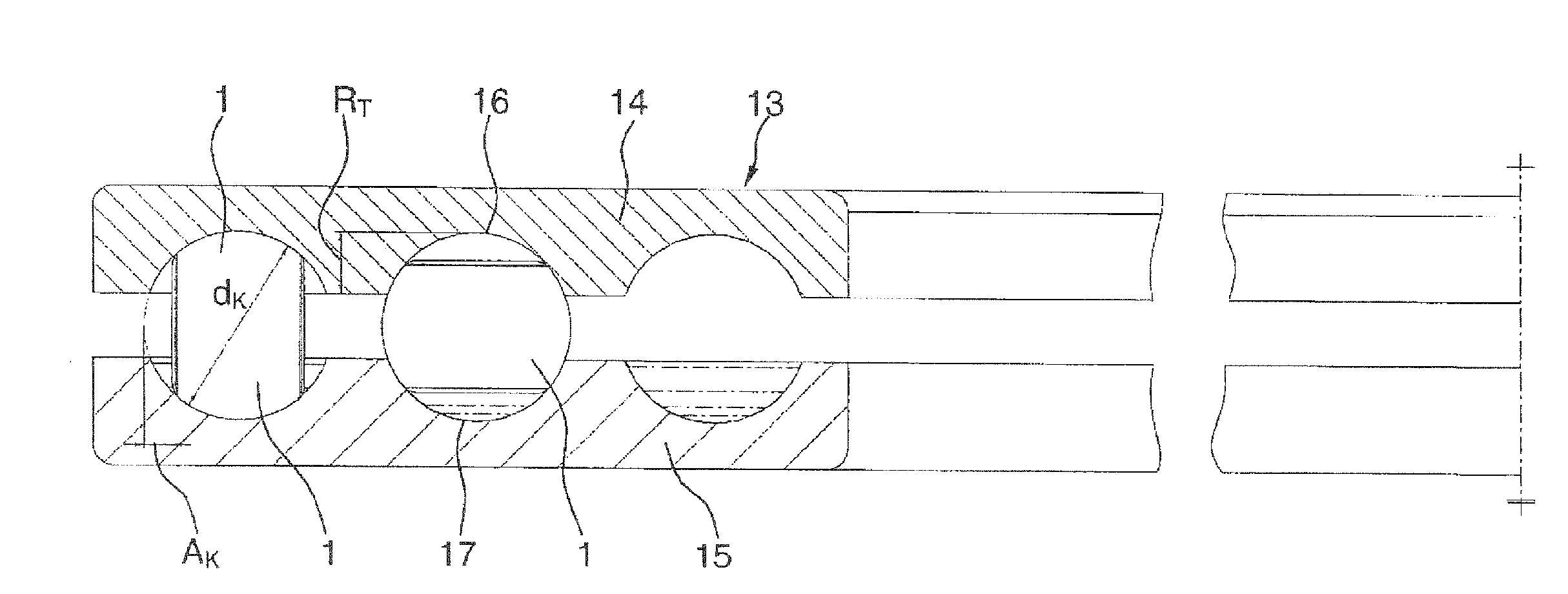
[0008]According to the invention, in a method according to the preamble of claim 1, this object is achieved in that the cut-off blank segments have a volume, as a result of which, during their compression molding, on the one hand, an approximately tangential raceway transition from one ball roller half to the other ball roller half and, on the other hand, material fibers running beneath the running surfaces of the ball rollers parallel or approximately parallel to these running surfaces are obtained, and in that the grinding of the ball roller blanks to their final dimensions takes place in a horizontal ball grinding machine fed solely with ball roller blanks of identical size.

[0009]The invention is thus based on the recognition that, by the blank segments being cut to length exactly from the round wire used or on account of the accompanying accurate determination of volume of the blank segments, it is possible, during the compression molding of the ball roller blanks, to avoid effe...


PUM

PropertyMeasurementUnit
Fractionaaaaaaaaaa
Lengthaaaaaaaaaa
Diameteraaaaaaaaaa

Abstract

A method for producing ball rollers. The following method steps are performed to produce the ball rollers: (A) cutting unfinished sections at a defined length from a round wire that has a defined diameter, (B) compression molding ball roller blanks that have end face depressions in the form of a die tool, and (C) grinding the ball roller blanks to the desired final dimensions in a ball grinding machine. The cut-off unfinished sections have a volume by which during compression molding an approximately tangential raceway transition from one ball roller half to the other ball roller half and material fibers extending under the running surfaces of the ball rollers parallel or approximately parallel to the running surfaces arise. In addition, the ball roller blanks are ground to the final dimensions in a horizontal ball grinding machine loaded exclusively with ball roller blanks of the same size.

Description

FIELD OF THE INVENTION[0001]The invention relates to a method for producing the rolling elements of a ball roller hearing, the rolling elements of which are designed as ball rollers.BACKGROUND OF THE INVENTION[0002]Ball roller bearings are rolling bearings with special rolling elements which are designed as ball rollers and which, starting from a basic spherical shape, have in each case two side faces which are flattened from this basic spherical shape and are arranged parallel to one another and between which the running surfaces of the ball rollers are in each case arranged. Ball roller bearings of this type have long been known in various embodiments, for example, from DE 311 317 A or DE 42 34 195 A1 and are distinguished, above all, in that, by virtue of the special design of their rolling elements, as compared with ball bearings of identical type, either they can be filled with a larger number of rolling elements and thereby have a higher load-bearing capacity (upgrading) or ca...

Claims


Application Information

Patent Timeline
IPC IPC(8): B21K1/02B24B9/00
CPCB21K1/02B24B11/06Y10T29/49694Y10T29/49636F16C33/36B21J1/025
Inventor BESENBECK, KURTDOEPPLING, HORSTHOFMANN, HEINRICH
Owner SCHAEFFLER TECH AG & CO KG
Why Eureka
Try Eureka