Traction motor

a traction motor and rotor technology, applied in the direction of synchronous motors, magnetic circuit rotating parts, magnetic circuit shape/form/construction, etc., can solve the problems of reducing the operating speed, reducing the productivity of vehicles, and so as to reduce the mean time between failures of the rotor and increase the threshold speed. , the effect of reducing the stress of the peak end ring

Active Publication Date: 2011-10-20
GE GLOBAL SOURCING LLC
View PDF2 Cites 13 Cited by
  • Summary
  • Abstract
  • Description
  • Claims
  • Application Information

AI Technical Summary

Benefits of technology

[0004]Accordingly, to address the above issues, various embodiments of a rotor of an induction motor are described herein. For example, in one embodiment, a rotor for an induction motor may comprise a punching assembly, a plurality of conductive bars, and an end-ring. The plurality of conductive bars may be substantially parallel to an axis of the rotor and connected to the punching assembly at a periphery of the punching assembly. Each conductive bar includes an end connected to the end-ring. The end-ring comprises a punching side having a punching surface facing the punching assembly and a housing side having a housing surface opposite the punching surface. The end-ring may be thicker on the punching side than the housing side. In this manner, the peak end ring stresses may be reduced at higher speeds and the mean time between failures of the rotor may be increased. Alternatively, the threshold speed may be increased and the top speed of the off-highway vehicle may be increased for a given expected mean time between failures of the rotor.

Problems solved by technology

Over time, the stresses may fatigue the end rings of the rotor and the rotor may fail, causing down-time and lost productivity for the vehicle.
However, reducing the operating speed leads to still other disadvantages, especially with regard to OHVs where increased speeds are increasingly being demanded.

Method used


Image

  • Traction motor
  • Traction motor
  • Traction motor

Examples


Embodiment Construction

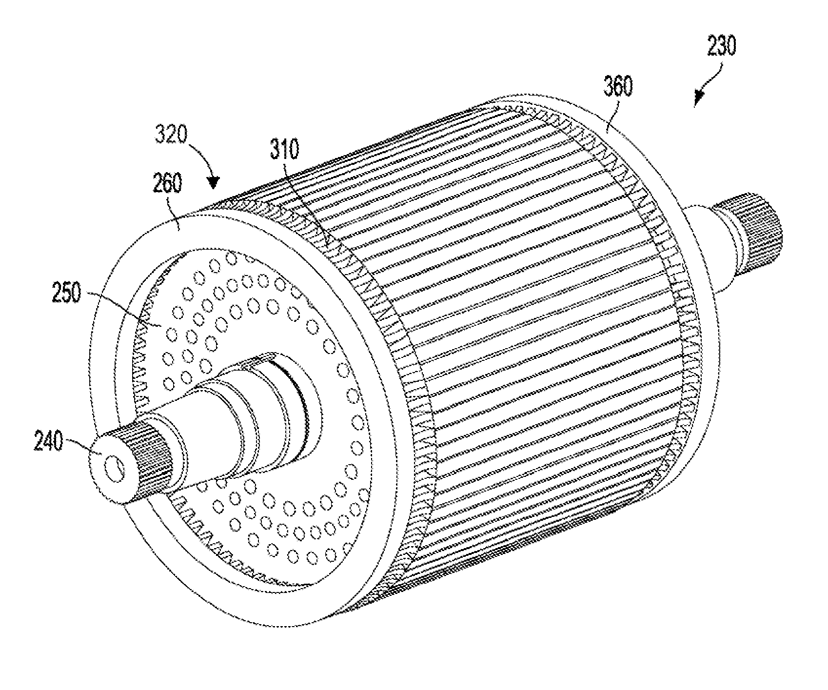
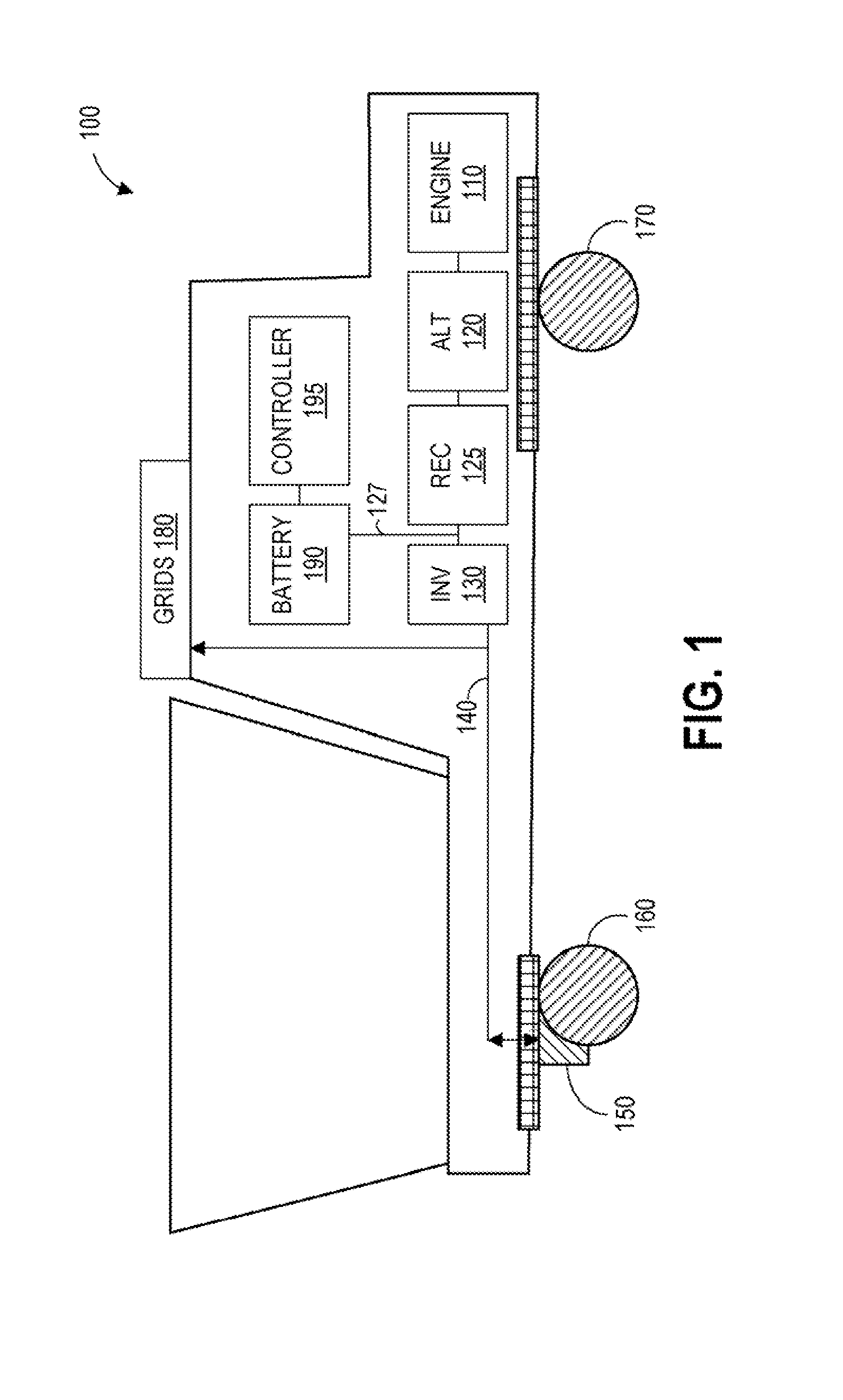
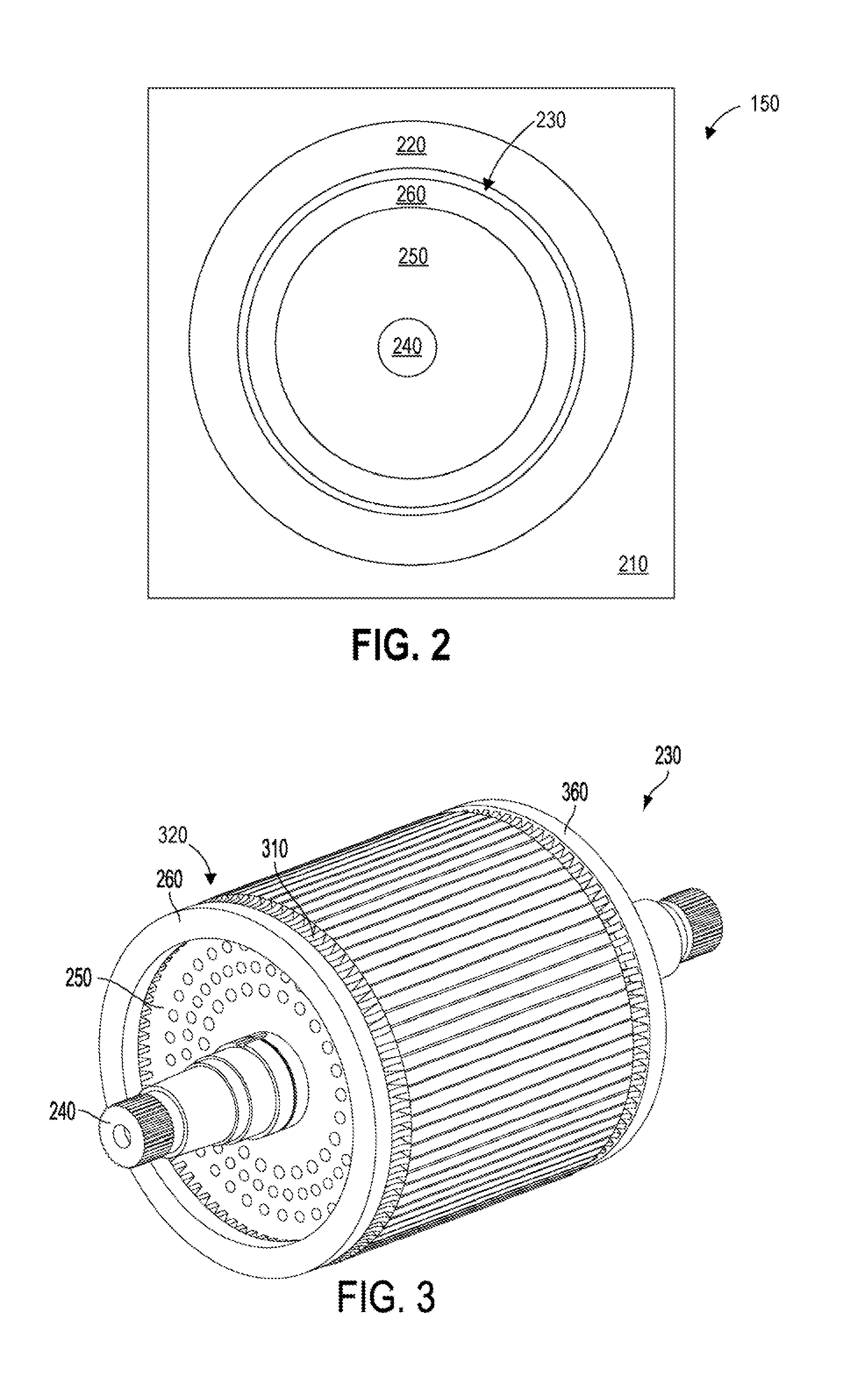
[0013]Productivity of off-highway vehicles may be increased when the top speed of the vehicle can be increased. FIG. 1 shows an example embodiment of an off-highway vehicle, specifically, FIG. 1 shows a mining truck. The mining truck includes a diesel-electric power source coupled to a traction motor coupled to a wheel of the mining truck. The traction motor provides torque to the wheel, so the top speed of the vehicle may be determined by a threshold speed of the traction motor. An example embodiment of a traction motor is illustrated in FIG. 2. The traction motor may be an alternating current (AC) induction motor including a stator and a rotor. FIG. 3 shows an example embodiment of a rotor comprising an end-ring. During operation of the traction motor, the end-ring of the rotor is subjected to a variety of stresses that may fatigue the end-ring. The shape of the end-ring may reduce stresses of the end-ring for a given speed of the traction motor. FIGS. 4-5 and 7 show different vie...


PUM


Abstract

In one embodiment, a rotor for an induction motor comprises a punching assembly, a plurality of conductive bars, and an end-ring. The plurality of conductive bars may be substantially parallel to an axis of the rotor and connected to the punching assembly at a periphery of the punching assembly. Each conductive bar includes an end connected to the end-ring. The end-ring comprises a punching side having a surface facing the punching assembly and a housing side having a surface opposite the punching surface. The end-ring may be thicker on the punching side than the housing side. In this manner, the peak end ring stresses may be reduced at higher speeds and the mean time between failures of the rotor may be increased. Alternatively, the threshold speed may be increased and the top-speed of the off-highway vehicle may be increased for a given expected mean time between failures of the rotor.

Description

FIELD[0001]Certain embodiments of the subject matter disclosed herein relate to a traction motor for a vehicle, such as an off-highway vehicle.BACKGROUND[0002]Off-highway vehicles (OHVs), such as railway locomotives, mining trucks, and excavators, may be utilized to move a payload from one location to a different location. It may be desirable to increase the top speed of the off-highway vehicle to increase the productivity of the vehicle as measured by payload moved per unit time. One embodiment of an off-highway vehicle includes a diesel-electric power source coupled to a traction motor coupled to a wheel of the off-highway vehicle. The traction motor applies torque to the wheel so the vehicle speed may be increased as the speed of the traction motor is increased. In one embodiment of a traction motor, the traction motor is an alternating current (AC) induction motor including a stator and a rotor. The stator includes field windings that set up a rotating magnetic field around the ...

Claims


Application Information

Patent Timeline
Patent Type & Authority Applications(United States)
IPC IPC(8): H02K17/16
CPCH02K17/165
Inventor VALLEJO, CARLOS A.
Owner GE GLOBAL SOURCING LLC
Why Eureka
Try Eureka