Coolant nozzle having function of automatically eliminating clogging by foreign matter

a technology of foreign matter and cooling nozzle, which is applied in the field of cooling nozzle, can solve the problems of reducing the number of man-hours, increasing the cost of installation of air supply means or maintenance of filters, and reducing the delivery time. , to achieve the effect of increasing the mean time between failures (mtbf), high cos

Active Publication Date: 2017-09-26
FANUC LTD
View PDF4 Cites 2 Cited by
  • Summary
  • Abstract
  • Description
  • Claims
  • Application Information

AI Technical Summary

Benefits of technology

[0013]According to the present invention, a device configuration such as air supply means need not be provided around the coolant nozzle, so that accumulation of foreign matter on the discharge port in the coolant nozzle can be suppressed without entailing high costs. Since the nozzle does not require regular maintenance, moreover, the mean time between failures (MTBF) increases.

Problems solved by technology

As the coolant containing the foreign matter circulates, the foreign matter accumulates on the coolant nozzle, resulting in a reduction in delivery.
Although the delivery can be restored by removing the foreign matter from the opening of the coolant nozzle manually or by a tool, however, maintenance to be performed at regular intervals requires a large number of man-hours.
However, this countermeasure additionally requires costs for the installation of the air supply means or maintenance of the filter.

Method used


Image

  • Coolant nozzle having function of automatically eliminating clogging by foreign matter
  • Coolant nozzle having function of automatically eliminating clogging by foreign matter
  • Coolant nozzle having function of automatically eliminating clogging by foreign matter

Examples


first embodiment

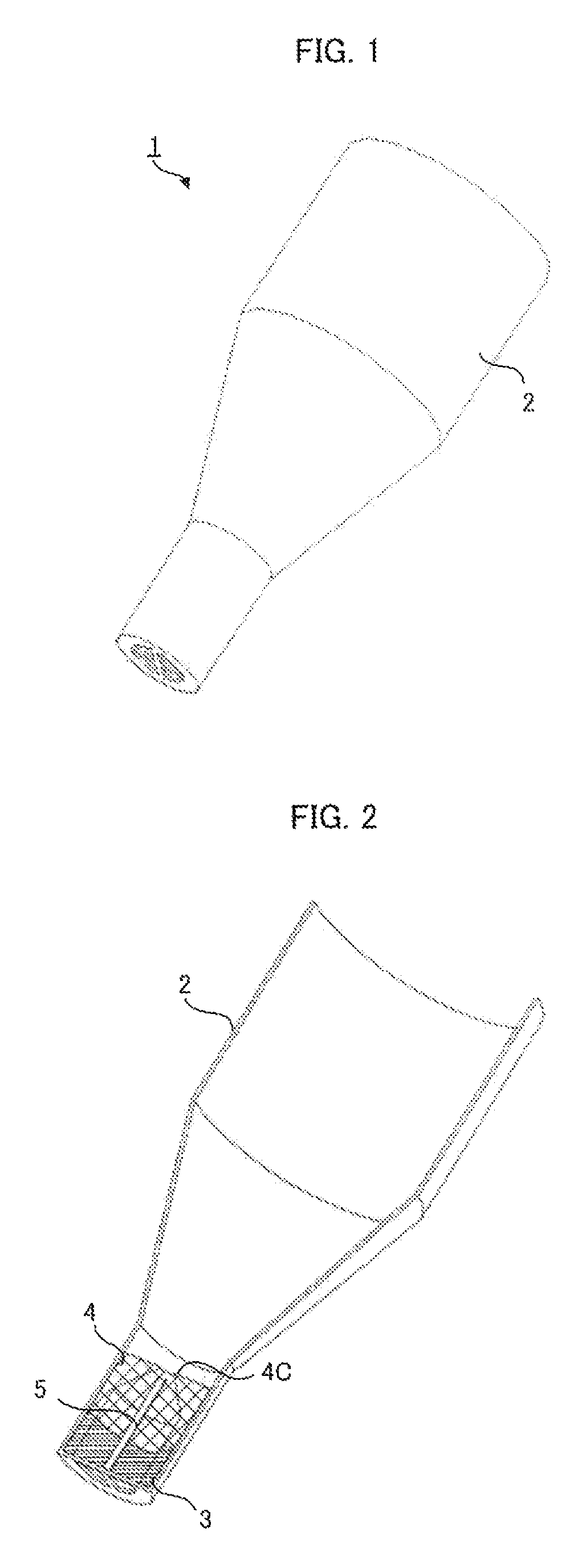
[0034]a coolant nozzle according to the present invention will first be described with reference to FIGS. 1 to 9.

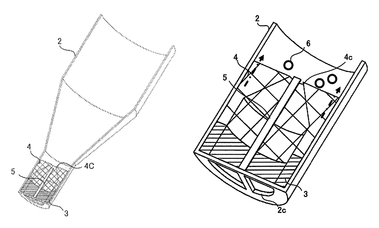
[0035]As shown in FIGS. 1 and 2, a coolant nozzle 1 comprises an outer nozzle (outer tube 2), elastic body 3, inner nozzle (inner tube 4), and projecting member (push rod 5).

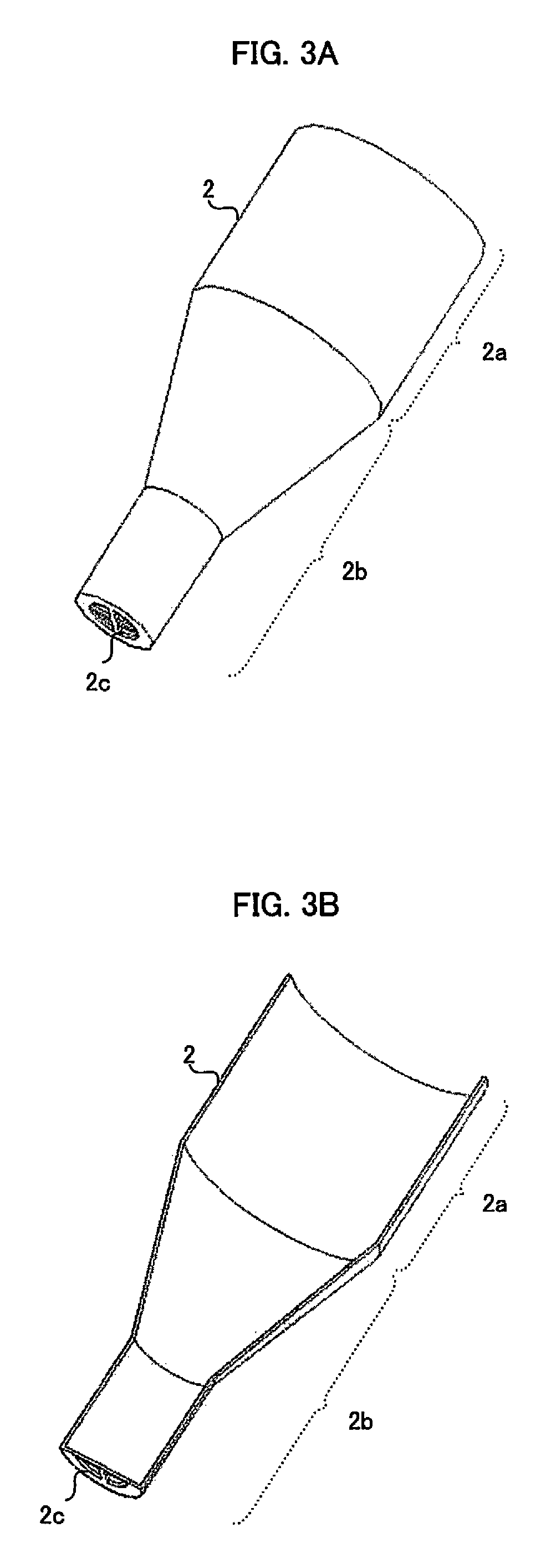
[0036]As shown in FIGS. 3A and 3B, the outer tube 2 has a shape that combines a cylindrical portion 2a and a funnel-shaped portion 2b. The distal end of the funnel-shaped portion 2b is formed as a discharge port 2c for a coolant. During machining by a machine tool, the coolant stored in a dedicated tank or the like is supplied through a pipe to the cylindrical portion 2a connected to the pipe under pressure from drive means such as a discharge pump. Then, the coolant is passed through the funnel-shaped portion 2b and jetted from the discharge port 2c toward a cutting point or a cutting tool.

[0037]The elastic body 3 is formed of an elastic material or member such as rubber and has a cylindrical shape, ...

second embodiment

[0046]the coolant nozzle according to the present invention will now be described with reference to FIG. 10.

[0047]In the coolant nozzle according to the first embodiment, the elastic body 3 is disposed so as to be exposed to the interior of the coolant nozzle through the nozzle opening 4c. In this embodiment, however, an inner wall 2d is provided inside an outer tube 2 so as to surround a discharge port 2c, and an elastic body 3 is disposed in a closed space surrounded by the outer tube 2, the inner wall 2d, and the lower end surface of an inner tube 4.

[0048]With this configuration, a coolant or foreign matter can be prevented from getting into the space around the elastic body 3, so that degradation and malfunctioning of the elastic body 3 can be avoided.

third embodiment

[0049]the coolant nozzle according to the present invention will now be described with reference to FIG. 11.

[0050]In this embodiment, a component of a nozzle 1 is provided with a mark in a position representative of a state in which a coolant is normally discharged. Based on the mark position, an operator is informed of clogging of foreign matter 6 and a change of the flow rate of the coolant.

[0051]To attain this, as shown in FIG. 11, the distal end portion of an outer tube 2 is provided with a first mark 2e and a slit 2f, which is disposed near the first mark 2e and extends long in the direction of movement of an inner tube 4 in the outer tube 2. On the other hand, the inner tube 4 located in the distal end portion of the outer tube 2 is provided with a second mark 4d in a position in which the slit 2f in the distal end portion of the outer tube 2 is passed.

[0052]As shown in FIG. 12, the first mark 2e attached to the distal end portion of the outer tube 2 and the second mark 4d on ...


PUM


Abstract

A nozzle through which a liquid coolant is discharged is provided with an outer tube, a projecting member and an inner tube disposed inside the outer tube, and an elastic body disposed between the inner tube and a discharge port of the outer tube. If foreign matter accumulates on a nozzle opening of the inner tube, the elastic body is compressed by the inner tube under the pressure of the coolant, so that the inner tube moves toward the discharge port. Consequently, the projecting member penetrates the nozzle opening, thereby automatically removing the foreign matter accumulated on the nozzle opening.

Description

RELATED APPLICATIONS[0001]The present application claims priority to Japanese Application Number 2014-204595, filed Oct. 3, 2014, the disclosure of which is hereby incorporated by reference herein in its entirety.BACKGROUND OF THE INVENTION[0002]Field of the Invention[0003]The present invention relates to a coolant nozzle, and more particularly, to a coolant nozzle having a function of automatically eliminating clogging by foreign matter.[0004]Description of the Related Art[0005]A cutting fluid (coolant) of which lubrication, cooling, and chip removal effects can be expected is used in many cases of cutting work and grinding work using a machine tool. The coolant stored in a dedicated tank or the like reaches a pipe via drive means such as a discharge pump and is then jetted from the tip end of a nozzle on an extension of the pipe toward a cutting point or a cutting tool.[0006]The nozzle for jetting the coolant is generally called a coolant nozzle. The coolant is supplied toward the...

Claims


Application Information

Patent Timeline
Patent Type & Authority Patents(United States)
IPC IPC(8): B05B15/02B24B55/02B23Q11/10B23B27/10B05B1/30B05B1/00B05B12/08B05B15/00
CPCB24B55/02B05B1/00B05B1/3006B05B12/085B05B15/008B05B15/02B05B15/0208B05B15/0216B05B15/0225B05B15/0233B23B27/10B23Q11/1076Y10S239/12Y10S239/19B05B15/5223B05B15/40B05B15/52B05B15/522B05B15/5225
Inventor KAKUMU, MASAHIRO
Owner FANUC LTD
Why Eureka
Try Eureka