Permanent magnetic assembly for

Inactive Publication Date: 2011-11-10
KONINKLIJKE PHILIPS ELECTRONICS NV
View PDF14 Cites 0 Cited by
  • Summary
  • Abstract
  • Description
  • Claims
  • Application Information

AI Technical Summary

Benefits of technology

[0005]It is therefore an object of the present invention to provide an arrangement of the kind mentioned initially and a permanent magnetic assembly in particular for use in

Problems solved by technology

Such an arrangement has shown the disadvantage that the efficiency of the magnetic selection means is rather low so that the permanent magnets need to be sized in a very large scale in order to produce the desired high magnetic gradient of the selection field.
This is in particular disadvantageou

Method used


Image

  • Permanent magnetic assembly for
  • Permanent magnetic assembly for
  • Permanent magnetic assembly for

Examples


Example

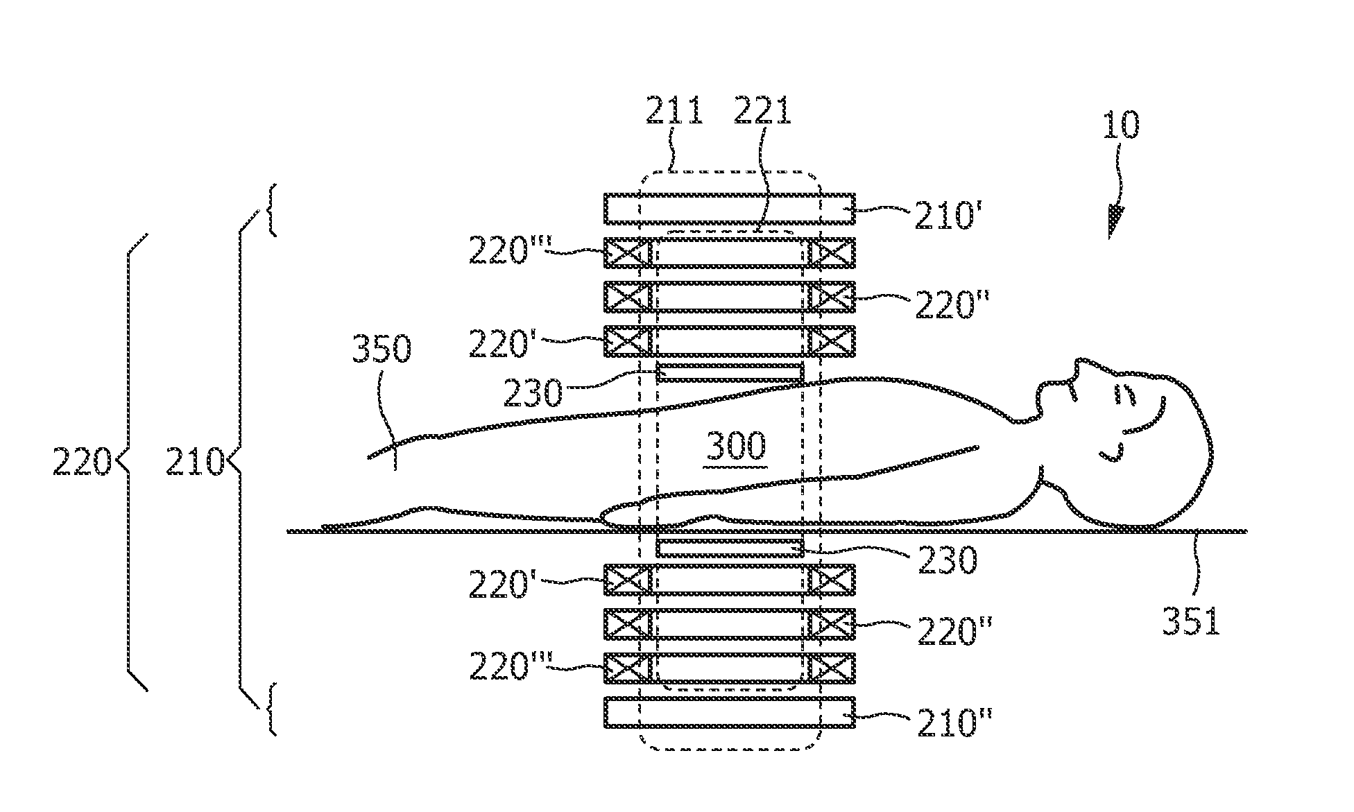
[0034]FIG. 1 shows an arbitrary object to be examined by means of a MPI arrangement 10. The reference numeral 350 in FIG. 1 denotes an object, in this case a human or animal patient, who is arranged on a patient table 351, only part of the top of which is shown. Prior to the application of the method according to the present invention, magnetic particles 100 (not shown in FIG. 1) are arranged in a region of action 300 of the inventive arrangement 10. Especially prior to a therapeutical and / or diagnostical treatment of, for example, a tumor, the magnetic particles 100 are positioned in the region of action 300, e.g. by means of a liquid (not shown) comprising the magnetic particles 100 which is injected into the body of the patient 350.

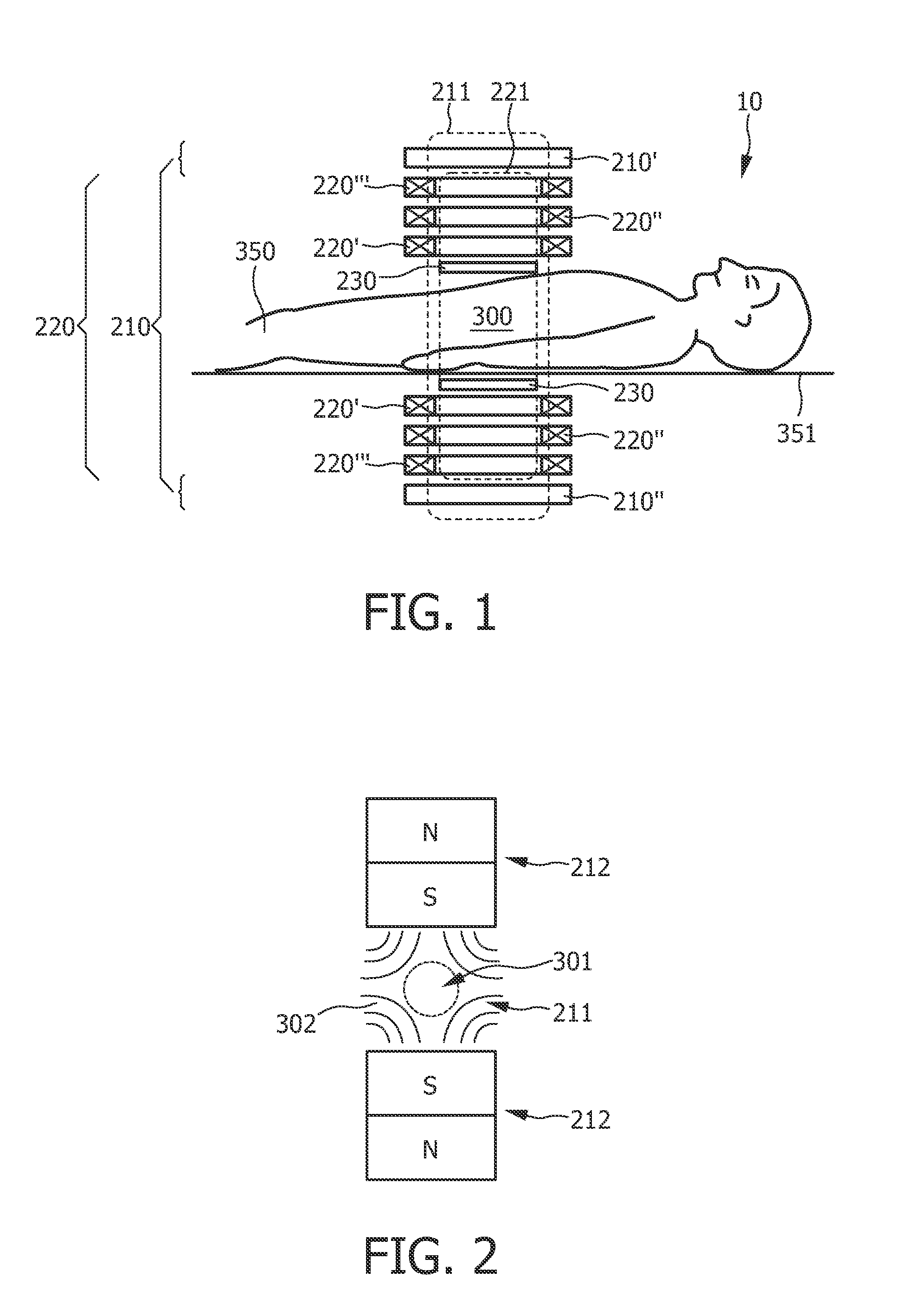
[0035]FIG. 2 shows the physical principal of generating the magnetic selection field 211 according to the prior art with two permanent magnets 212. The two permanent magnets 212 together form a selection means 210 whose range defines the region of acti...


PUM


Abstract

The present invention relates to an arrangement (10) for influencing and/or detecting magnetic particles in a region of action (300). The arrangement (10) comprises selection means (210) for generating a magnetic selection field (211) having a pattern in space of its magnetic field strength such that a first sub-zone (301) having a low magnetic field strength and a second sub zone (302) having a higher magnetic field strength are formed in the region of action (300), drive means (220) for changing the position in space of the two sub-zones (301, 302) in the region of action (300) by means of a magnetic drive field (221) so that the magnetization of the magnetic material changes locally, and receiving means (230) for acquiring detection signals, which detection signals depend on the magnetization in the region of action (300), which magnetization is influenced by the change in the position in space of the first and second sub-zone (301, 302). The selection means (210) comprises a permanent magnetic assembly having at least one permanent magnetic unit (213) comprising a plurality of magnetic sub-elements (214) wherein the magnetic sub-elements (214) have individually fixed magnetization orientation, and are bonded together to form said at least one permanent magnetic unit (213).

Description

FIELD OF THE INVENTION[0001]The present invention relates to an arrangement for influencing and / or detecting magnetic particles in a region of action. The present invention further relates a permanent magnetic assembly, in particular for use in an arrangement for influencing and / or detecting magnetic particles in a region of action.BACKGROUND OF THE INVENTION[0002]An arrangement of this kind is known from German patent application DE 101 51 778 A1. In the arrangement described in that publication, first of all a magnetic selection field having a spatial distribution of the magnetic field strength is generated by magnetic selection means such that a first sub-zone, which is also called magnetic field-free point, having a relatively low magnetic field strength and a second sub-zone having a relatively high magnetic field strength are formed in the examination zone. The position in space of the sub-zones in the examination zone is then shifted, so that the magnetization of the particle...

Claims


Application Information

Patent Timeline
IPC IPC(8): G01R33/24G01R33/383
CPCA61B5/0515A61B5/055G01R33/383G01R33/14G01R33/3802G01R33/022
Inventor TIMINGER, HOLGERWEIZENECKER, JURGENGLEICH, BERNHARD
Owner KONINKLIJKE PHILIPS ELECTRONICS NV
Why Eureka
Try Eureka