Apparatus and methods for separating and joining tubulars in a wellbore

Inactive Publication Date: 2005-02-08
WEATHERFORD TECH HLDG LLC
View PDF177 Cites 19 Cited by
  • Summary
  • Abstract
  • Description
  • Claims
  • Application Information

AI Technical Summary

Benefits of technology

In yet another aspect, the invention provides apparatus and methods to join tubulars in a wellbore providing

Problems solved by technology

In some instances, tools or tubular strings become stuck in the wellbore leading to a “fishing” operation to locate and remove the stuck portion of the apparatus.
Because the interior of a tubular typically provides a pathway clear of obstructions, and because any annular space around a tubular is limited, prior art devices for downhole tubular cutting typically operate within the interior of the tubular and cut the wall of the tubular from the inside towards the outside.
For instance, the knives are constructed to swing outward from a pivot point on the body of the cutting tool and in certain instances, the knives can become jammed between the cutting tool and the interior of the tubular to be cut.
In other instances, the cutting members can become jammed in a manner which prevents them from retracting once the cutting operation is complete.
In still other examples, the swinging cutting members can become jammed with the lower portion of tubular after it has been separated from the upper portion thereof.
Additionally, this type of cutter creates cuttings that are difficult t

Method used


Image

  • Apparatus and methods for separating and joining tubulars in a wellbore
  • Apparatus and methods for separating and joining tubulars in a wellbore
  • Apparatus and methods for separating and joining tubulars in a wellbore

Examples


Embodiment Construction

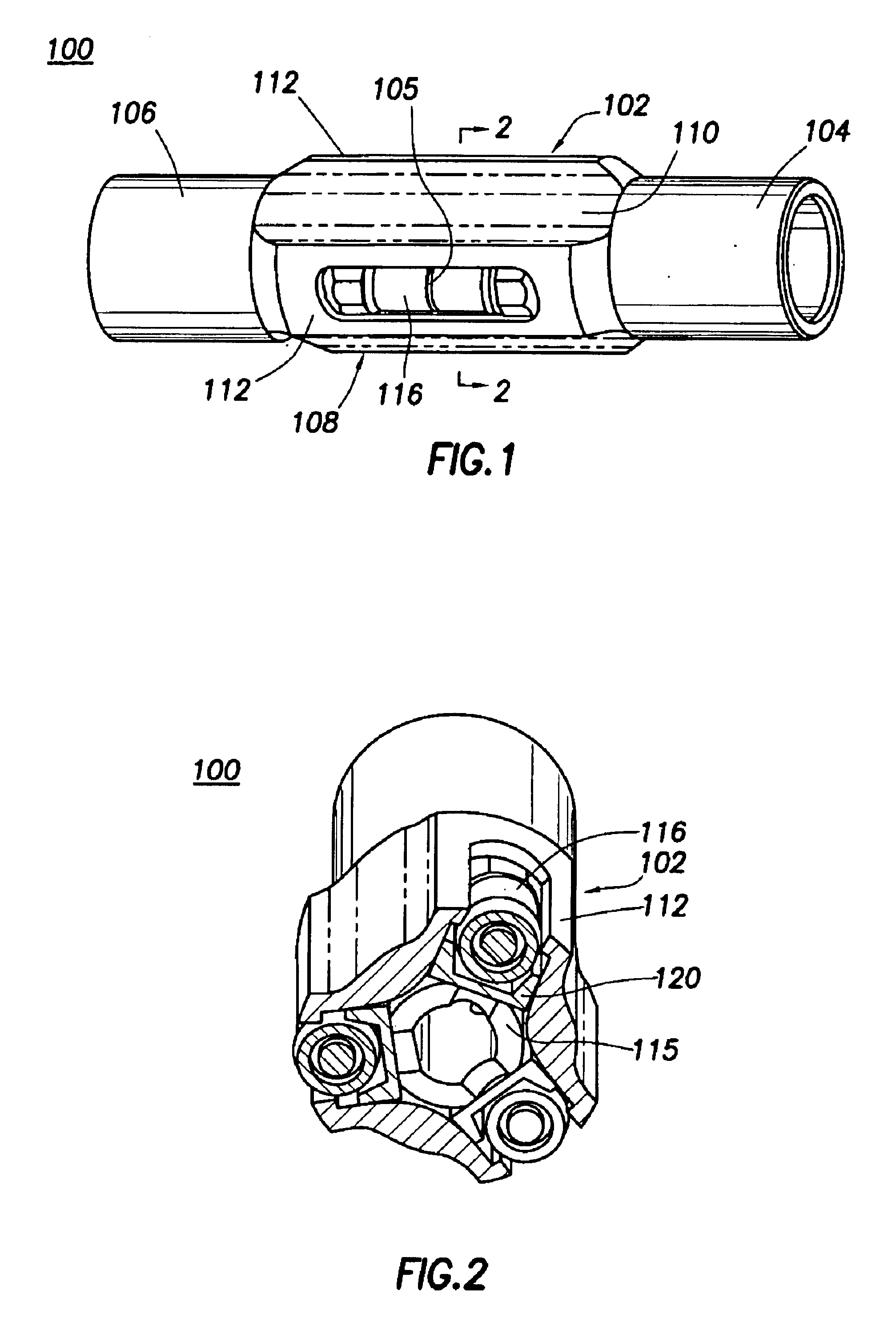
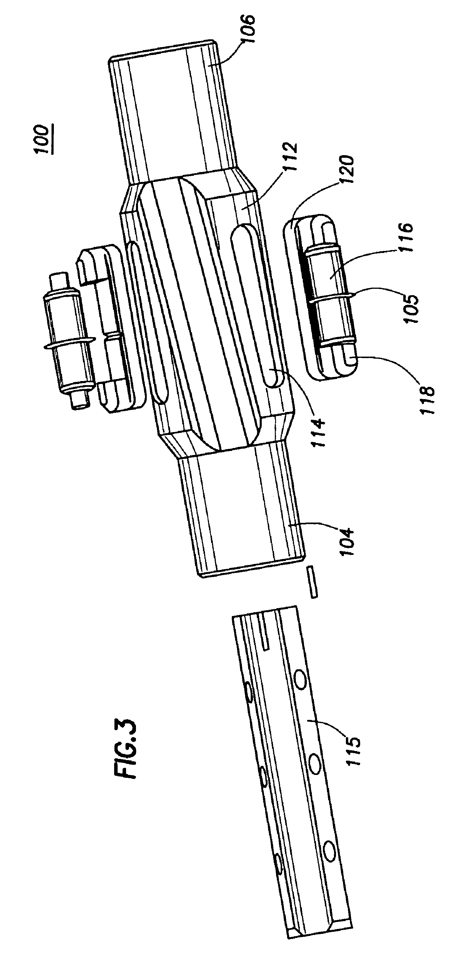
FIGS. 1 and 2 are perspective views of the cutting tool 100 of the present invention. FIG. 3 is an exploded view thereof. The tool 100 has a body 102 which is hollow and generally tubular with conventional screw-threaded end connectors 104 and 106 for connection to other components (not shown) of a downhole assembly. The end connectors 104 and 106 are of a reduced diameter (compared to the outside diameter of the longitudinally central body part 108 of the tool 100), and together with three longitudinal flutes 110 on the central body part 108, allow the passage of fluids between the outside of the tool 100 and the interior of a tubular therearound (not shown). The central body part 108 has three lands 112 defined between the three flutes 110, each land 112 being formed with a respective recess 114 to hold a respective roller 116. Each of the recesses 114 has parallel sides and extends radially from the radially perforated tubular core 115 of the tool 100 to the exterior of the respe...


PUM


Abstract

The present invention provides methods and apparatus for cutting tubulars in a wellbore. In one aspect of the invention, a cutting tool having radially disposed rolling element cutters is provided for insertion into a wellbore to a predetermined depth where a tubular therearound will be cut into an upper and lower portion. The cutting tool is constructed and arranged to be rotated while the actuated cutters exert a force on the inside wall of the tubular, thereby severing the tubular therearound. In one aspect, the apparatus is run into the well on wireline which is capable of bearing the weight of the apparatus while supplying a source of electrical power to at least one downhole motor which operates at least one hydraulic pump. The hydraulic pump operates a slip assembly to fix the downhole apparatus within the wellbore prior to operation of the cutting tool. Thereafter, the pump operates a downhole motor to rotate the cutting tool while the cutters are actuated.

Description

BACKGROUND OF THE INVENTION1. Field of the InventionThe present invention relates to methods and apparatus for separating and joining tubulars in a wellbore; more particularly, the present invention relates to cutting a tubular in a wellbore using rotational and radial forces brought to bear against a wall of the tubular.2. Description of the Related ArtIn the completion and operation of hydrocarbon wells, it is often necessary to separate one piece of a downhole tubular from another piece in a wellbore. In most instances, bringing the tubular back to surface for a cutting operation is impossible and in all instances it is much more efficient in time and money to separate the pieces in the wellbore. The need to separate tubulars in a wellbore arises in different ways. For example, during drilling and completion of an oil well, tubulars and downhole tools mounted thereon are routinely inserted and removed from the wellbore. In some instances, tools or tubular strings become stuck in ...

Claims


Application Information

Patent Timeline
IPC IPC(8): E21B29/00E21B23/00E21B33/03E21B23/01E21B43/02E21B33/13E21B33/14E21B33/04E21B43/10
CPCE21B23/00E21B23/01E21B43/105E21B33/0422E21B33/146E21B29/005
Inventor SIMPSON, NEIL A. A.TRAHAN, KEVIN O.
Owner WEATHERFORD TECH HLDG LLC
Why Eureka
Try Eureka