Collimator module, x-ray detector, x-ray CT device, and assembling method of collimator module
- Summary
- Abstract
- Description
- Claims
- Application Information
AI Technical Summary
Benefits of technology
Problems solved by technology
Method used
Image
Examples
first embodiment
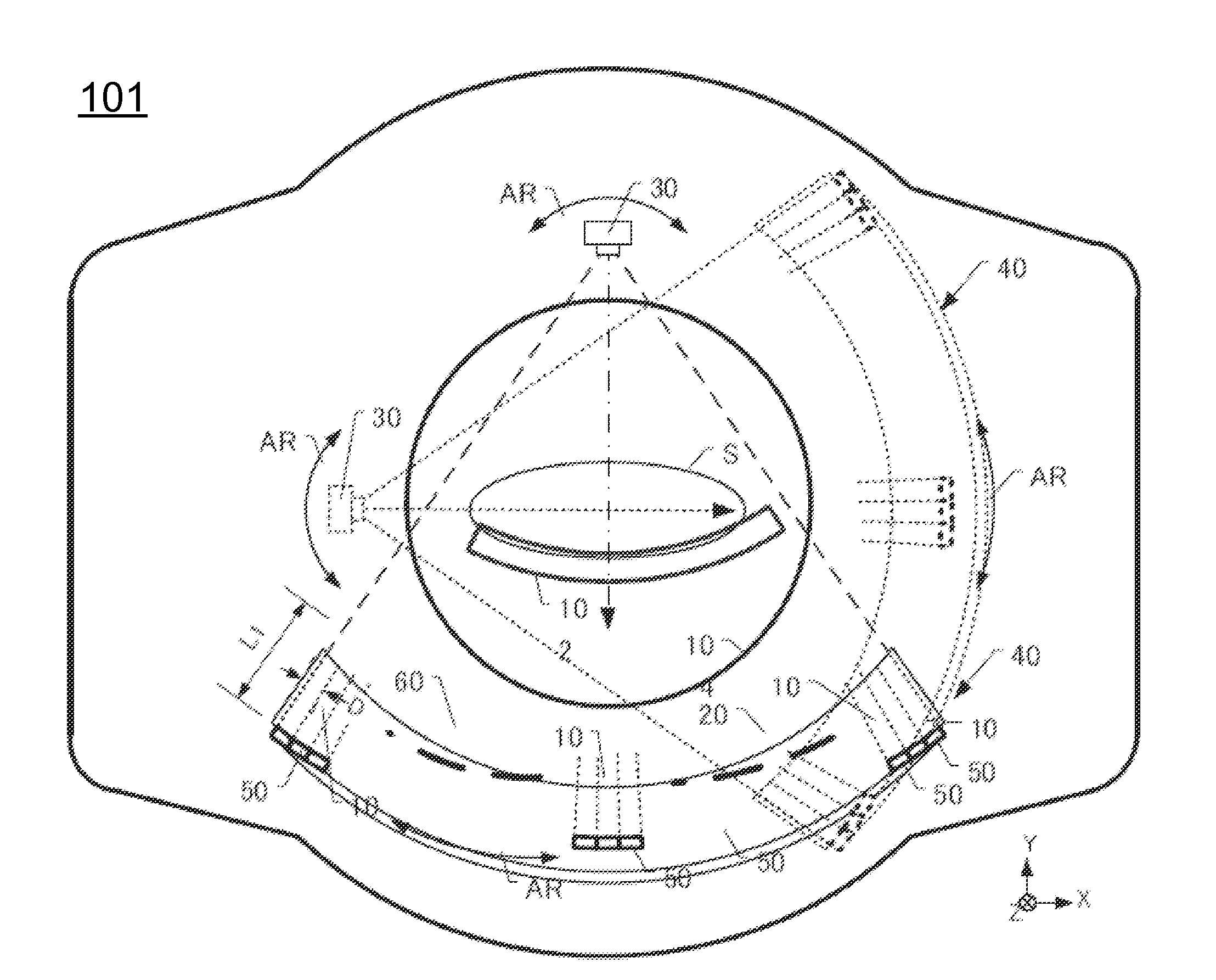
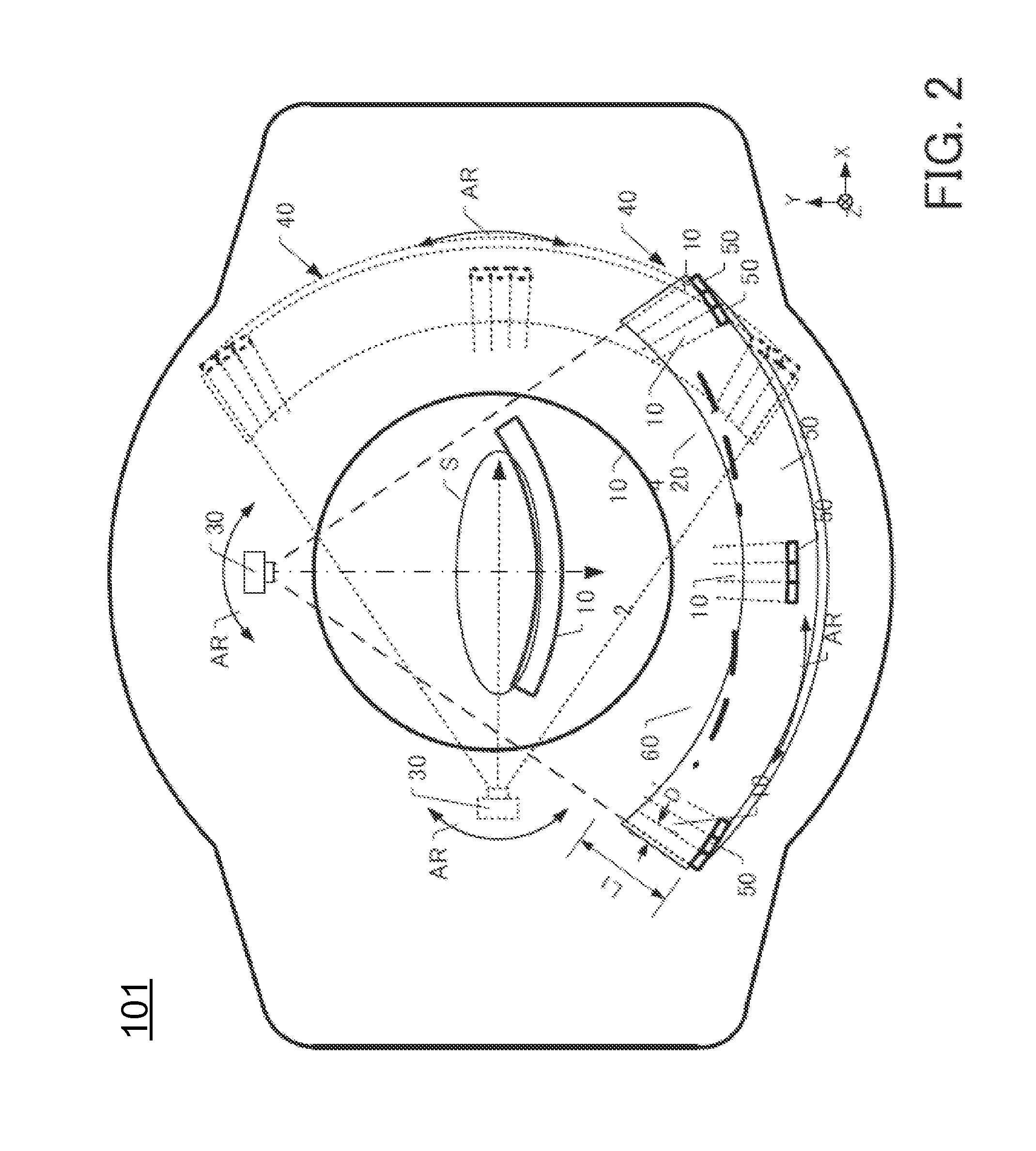
[0056]FIGS. 4A and 4B show the first collimator module 10A of a first embodiment. FIG. 4A is a plan view of the first collimator module 10A. FIG. 4B is a side view of the first collimator module 10A.
[0057]As shown in FIGS. 4A and 4B, the first collimator module 10A includes dozens of rectangle collimator single plates 11, a pair of blocks 12 formed at both distal ends in Z-axis direction of the collimator single plate 11, and a first incident side fixing sheet 13 and a first emission side fixing sheet 15 formed at both distal ends of the collimator single plate 11 and the blocks 12. In the first embodiment, the collimator single plate 11 is bonded to the blocks 12 by an adhesive, and the first incident side fixing sheet 13 and the first emission side fixing sheet 15 are bonded to the collimator single plate 11 and the blocks 12 by an adhesive. The bonding manner will be explained later by referring FIG. 12.
[0058]The first collimator module 10A has a size to be placed on the base 60 ...
second embodiment
[0075]FIGS. 8A and 8B are figures for explaining a second collimator module 10B of a second embodiment. FIG. 8A is a flat view of the second collimator module 10B. FIG. 8B is a side view of the second collimator module 10B.
[0076]As shown in FIGS. 8A and 8B, the second collimator module 10B has a configuration that four second incident side fixing sheets 14 and four second emission side fixing sheets 16 are fixed in addition to the first collimator module 10A of the first embodiment. Thus, the second collimator module 10B has the same configuration of the first embodiment except the second incident side fixing sheets 14 and the second emission side fixing sheets 16.
[0077]On respective one surfaces of the second incident side fixing sheet 14 and the second emission side fixing sheet 16, dozens of second grooves are formed with designated pitches respectively same as the first incident side fixing sheet 13 and the first emission side fixing sheet 15. For the second incident side fixing...
third embodiment
[0082]FIG. 9 is a figure for explaining a third collimator module 10C of the third embodiment. FIG. 9A is a flat view of the third collimator module 10C. FIG. 9B is a side view of the third collimator module 10C.
[0083]As shown in FIGS. 9A and 9B, the third collimator module 10C has a configuration that five third fixing sheets on incident side 17 and five third fixing sheets on emission side 19 are fixed in addition to the second collimator module 10B of the second embodiment. Thus, the third collimator module 10C has the same configuration of the second embodiment except the third incident side fixing sheet 17 and the third emission side fixing sheet 19.
[0084]The third incident side fixing sheet 17 and the third emission side fixing sheet 19 have dozens of third grooves on one surface with designated pitches respectively same as the first incident side fixing sheet 13 and the first emission side fixing sheet 15. CFRP having X-ray transmission property is also used for the third inc...
PUM
| Property | Measurement | Unit |
|---|---|---|
| Current | aaaaa | aaaaa |
Abstract
Description
Claims
Application Information
 - R&D
- Intellectual Property
- Life Sciences
- Materials
- Tech Scout
- Unparalleled Data Quality
- Higher Quality Content
- 60% Fewer Hallucinations
Browse by: Latest US Patents, China's latest patents, Technical Efficacy Thesaurus, Application Domain, Technology Topic, Popular Technical Reports.
© 2025 PatSnap. All rights reserved.Legal|Privacy policy|Modern Slavery Act Transparency Statement|Sitemap|About US| Contact US: help@patsnap.com


